Fire-resistant abrasion-proof inner lining structure for heat insulation surface of industrial furnace

A fire-resistant and wear-resistant, industrial furnace technology, applied in lining repair and other directions, can solve the problems of difficult construction quality control, cross fire, difficult maintenance, etc., and achieve the effects of easy control of installation quality, small quality difference, and convenient construction.

Inactive Publication Date: 2009-08-12
宜兴市张泽耐火电瓷厂有限公司
View PDF0 Cites 4 Cited by
  • Summary
  • Abstract
  • Description
  • Claims
  • Application Information

AI Technical Summary

Problems solved by technology

[0008] 5. If there is a problem with the pouring quality of the concrete construction body structure, it is easy to cause the construction body to fall off and the gap is too large, resulting in the phenomenon of string fire and the overheating of the outer wall (wall) of the industrial furnace (boiler), the equipment is easily damaged, and the shutdown rate is caused. high
[0009] 6. It is difficult to maintain the concrete construction structure after the quality of pouring has problems
[0010] Therefore, the construction procedure of the concrete construction body structure is cumbersome, the construction time is long, the construction difficulty is increased, and the construction quality is difficult to control

Method used


Image

  • Fire-resistant abrasion-proof inner lining structure for heat insulation surface of industrial furnace
  • Fire-resistant abrasion-proof inner lining structure for heat insulation surface of industrial furnace
  • Fire-resistant abrasion-proof inner lining structure for heat insulation surface of industrial furnace

Examples


Embodiment Construction

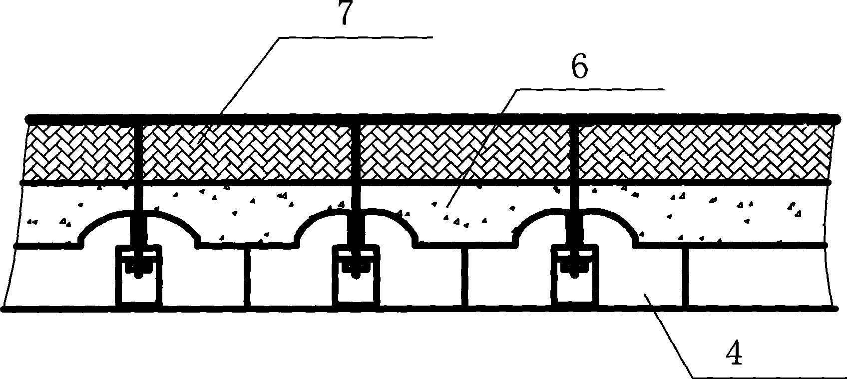
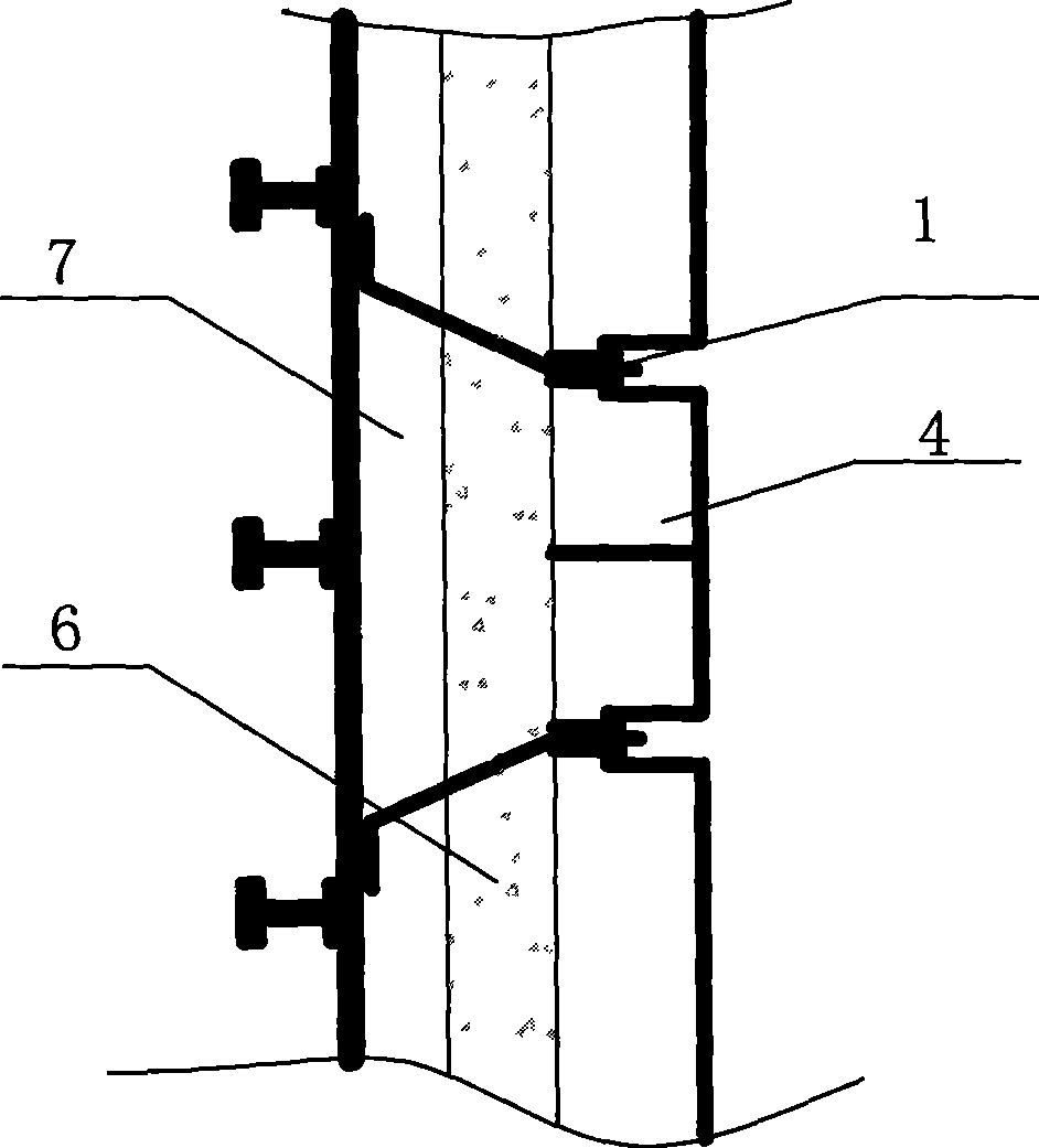
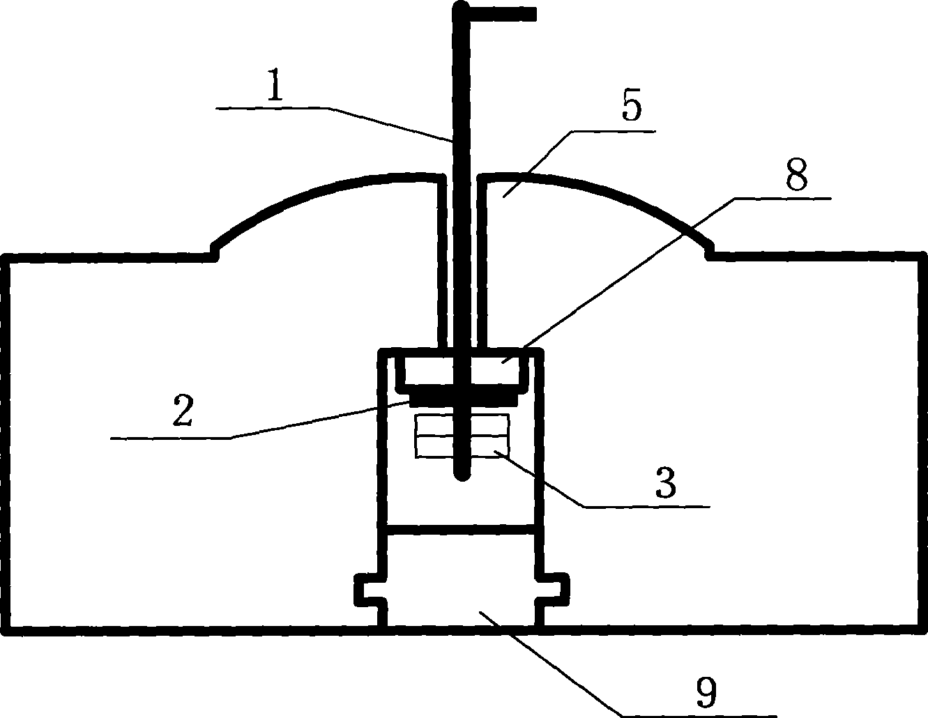
[0020] Such as Figure 1-Figure 3 As shown, first lay ceramic fiber bricks 7 and welded heat-resistant bolts 1 on the main support structure of the heat-insulating surface of the industrial furnace wall or furnace roof, then lay refractory and wear-resistant bricks 4, and then pour heat-insulating castables 6 on the inside, the present invention then It mainly includes heat-resistant bolts 1, heat-resistant flat pads 2, heat-resistant nuts 3 and wear-resistant bricks 4, wherein the refractory and wear-resistant bricks 4 are prefabricated, and there are stepped through holes 5 vertically in the refractory and wear-resistant bricks 4. The fastening end of the heat bolt 1 is L-shaped, which passes through the thermal insulation castable 6 and ceramic fiber brick 7 of the industrial furnace wall or roof, and is finally welded on the steel frame of the wall or furnace roof. The threaded end of the heat-resistant bolt 1 Pass through the stepped through hole 5 of the wear-resistant b...


PUM


Abstract

The invention discloses a refractory wear-resistant lining structure for the thermal insulation surface of an industrial furnace, which comprises a heat resistant bolt, a heat resistant flat cushion, a heat resistant nut and a refractory wear-resistant brick; the refractory and wear-resistant brick is prefabricated for forming; the inside of the refractory wear-resistant brick is provided with a stepped through hole vertically; the fastening end of the heat resistant bolt passes through the wall body of the industrial furnace or a heat insulation casting material and a ceramic fiber brick on the furnace top, and is welded onto a steel plate on the wall body or a steel frame on the furnace top; and the thread end of the heat resistant bolt passes through the stepped through hole of the refractory wear-resistant brick, is arranged into the heat resistant flat cushion and is locked by the heat resistant nut. The refractory wear-resistant lining structure is a novel structure for replacing the prior industrial furnace, in particular the wall body and the furnace top on the heat insulation surface of a circulating fluidized bed boiler. The invention adopts a fixed module type refractory wear-resistant brick structure; because the refractory wear-resistant brick is manufactured by a factory, the refractory wear-resistant brick is not limited by the site construction condition and has easy control in quality, convenient mass production, and small quality difference; and the refractory wear-resistant lining structure has convenient site construction, simple mounting and easy control of mounting quality, and also brings great convenience to overhauling.

Description

technical field [0001] The invention mainly relates to a lining structure, in particular to a thermal insulation surface lining of an industrial furnace. Background technique [0002] The traditional design and construction of the current insulation surface lining of industrial furnaces is to use heat-resistant nails to fix the insulation layer and fire-resistant and wear-resistant layer. The structural form of wear-resistant bricks. [0003] The construction of this liner has the following disadvantages: [0004] 1. Since the heat-resistant nails currently used are all Y-shaped, the construction difficulty of the insulation layer after welding the dense nails is increased, and generally it can only be applied by hand. In particular, some designs use hard insulation materials (bricks) as the insulation layer, and build hard insulation materials (bricks) between the densely distributed nails. The gap between the masonry is difficult to control, and the quality of insulation...

Claims


Application Information

Patent Timeline
Patent Type & Authority Applications(China)
IPC IPC(8): F27D1/16
Inventor 俞永平陈进良
Owner 宜兴市张泽耐火电瓷厂有限公司
Why Eureka
Try Eureka