Full self-control non-woven fabrics thermal compression welding device and method

A technology of hot-press welding and welding method, which is applied to the seams of textile materials, textiles and papermaking, mechanical processing/deformation, etc. The effect of low production cost

Active Publication Date: 2009-08-19
杭州珂瑞特新机械制造有限公司
View PDF1 Cites 25 Cited by
  • Summary
  • Abstract
  • Description
  • Claims
  • Application Information

AI Technical Summary

Problems solved by technology

The objective existence is that the above-mentioned ultrasonic welding device is only suitable for the welding of non-woven fabrics with less than 4 layers, and is not suitable for the welding of non-woven fabrics with more than 4 layers, especially on production lines with a speed of more than 120 meters per minute. The quality does not meet the tensile strength of the international industry standard, and all the products welded by the production line are scrapped

Method used


Image

  • Full self-control non-woven fabrics thermal compression welding device and method
  • Full self-control non-woven fabrics thermal compression welding device and method

Examples


Embodiment 1

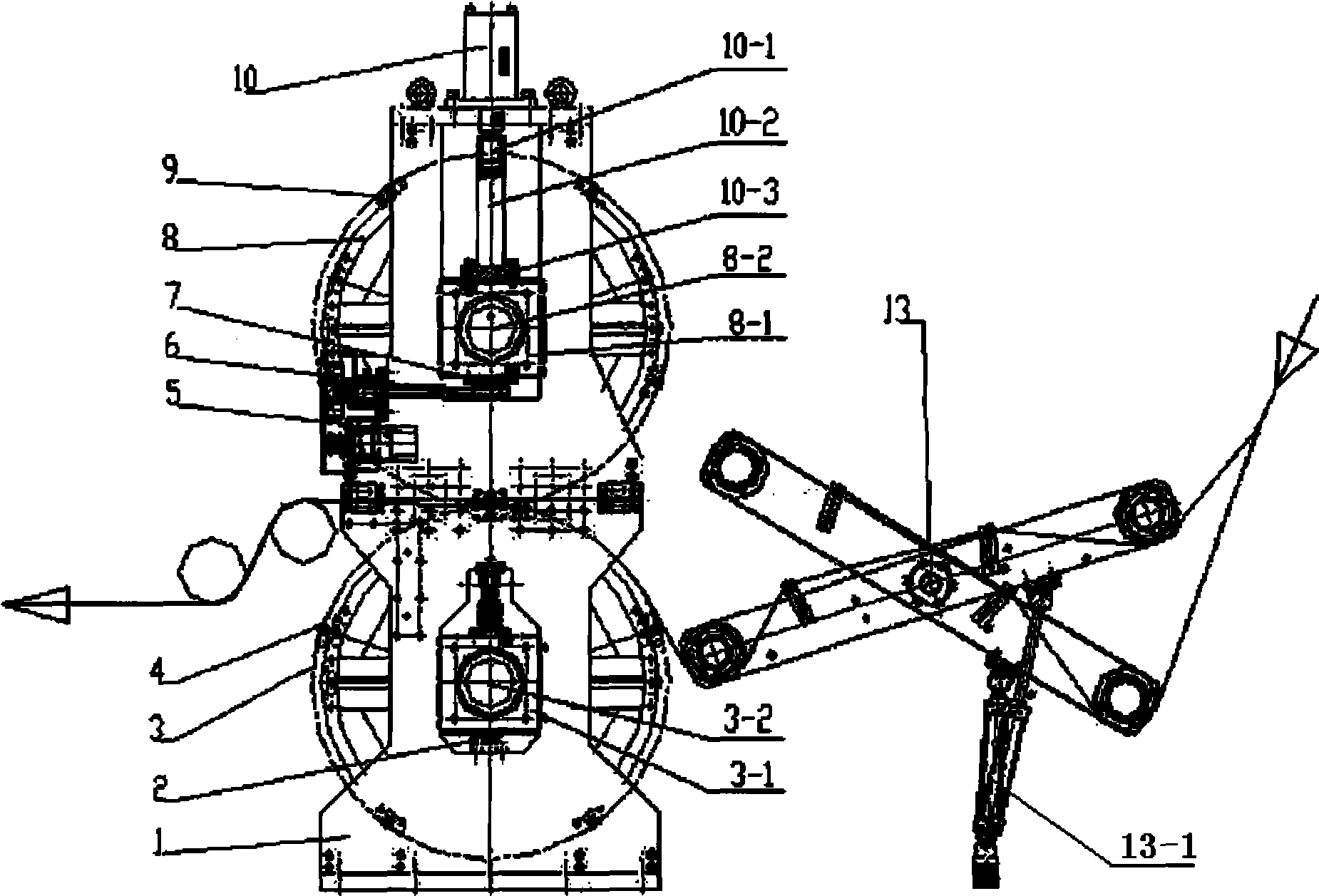
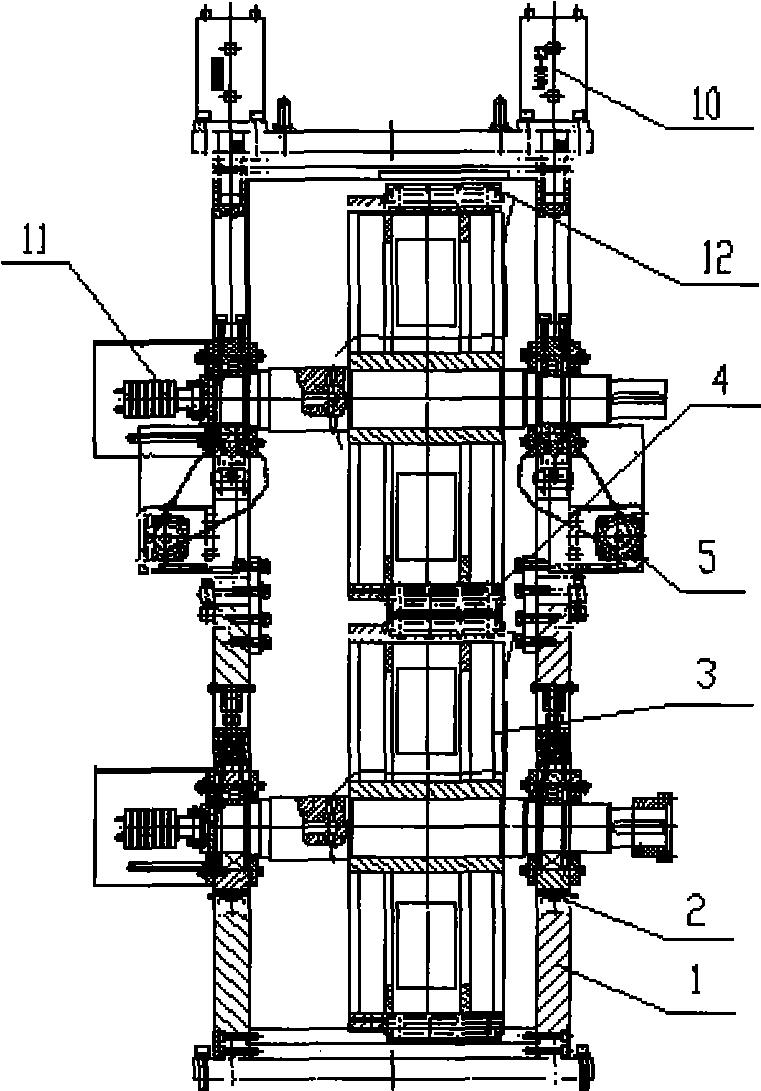
[0010] Embodiment 1: with reference to attached Figure 1~2 . Fully automatic non-woven hot-press welding device, which includes a PLC controller, a groove structure on the upper part of the frame 1, and a hole in the lower part, and the lower electric heating welding wheel 3 Axle 3-2 passes through the lower slider 3-1 and is located on the frame 1 In the lower hole and the lower end surface of the lower slider 3-1 is pressed on the pressure sensor 2, the upper electric heating welding wheel 8 axle 8-2 is located in the upper groove of the frame 1 through the upper slider 8-1 and the upper slider 8 -1 The lower end surface is located on the screw adjustment wedge 7 and the screw adjustment wedge 7 is driven by the stepper motor 5 through the transmission mechanism, the power supply end of the stepper motor 5 is controlled by the PLC controller, and the hydraulic cylinder 10 is located on the machine On the upper end of the frame 1, the piston 10-1 of the hydraulic cylinder 1...

Embodiment 2

[0011] Embodiment 2: On the basis of Embodiment 1, the welding method of the fully automatic non-woven fabric hot-press welding equipment, the welding pressure and welding temperature required for welding products are input into the PLC controller, and the welding program built in the PLC controller According to the pressure and welding temperature required for product welding, calculate the welding pressure of the product and the gap between the welding dies, and then according to the pressure value detected by the pressure sensor 2, under the rated working pressure set by the hydraulic cylinder 10, command the stepping motor 5 Adjust the screw rod adjustment wedge block 7 so that the welding gap between the welding dies reaches the gap required by the pressure setting value, and then welding can be carried out.


PUM


Abstract

The invention relates to rapid, convenient, intellectually-controlled full autocontrol nonwoven fabric hot-press welding equipment and a welding method. The full autocontrol nonwoven fabric hot-press welding equipment comprises a PLC controller, a stand, a lower electric heating welding wheel axle, an upper electric heating welding wheel axle, a step motor, an oil cylinder, wherein the upper part of the stand has a groove structure; the lower part of the stand is provided with a hole; the lower electric heating welding wheel axle is positioned in the hole of the lower part of the stand by a lower slide block; the lower end face of the lower slide block is pressed on a pressure sensor; the upper electric heating welding wheel axle is positioned in a groove of the upper part of the stand; the lower end face of an upper slide block is positioned on an adjustable oblique wedge block of a screw rod; the adjustable oblique wedge block of the screw rod passes through a transmission mechanism and is driven by the step motor; the power end of the step motor is controlled by the PLC controller; the oil hydraulic cylinder is positioned on the upper end of the stand; a piston of the oil hydraulic cylinder is connected with the upper slide block by a connecting rod and a connecting plate; and the operation of the oil hydraulic cylinder is controlled by the PLC controller. The equipment has the advantages of: 1, realizing the reliable welding of more than four layers of nonwoven fabric on a production line at an online speed of more than 120 meters per minutes; and 2, according to predetermined welding pressure and welding temperature, freely and automatically carrying out free micro-adjustment by online construction and the change of welding temperature and ambient temperature and ensuring pressure and temperature needed for high-efficient welding.

Description

technical field [0001] The invention relates to a fast, convenient, intelligently controlled fully automatic non-woven hot-press welding equipment and a welding method, belonging to the field of sanitary product equipment manufacturing. Background technique [0002] The applicant owns CN1807080A, titled "Ultrasonic welding device and welding method for adult incontinence pants", the embossed shaft is located in the shaft hole of the side box plate, the embossed block is located on the embossed shaft, the upper fixing plate is located on the side box plate, and the guide rail Distributed longitudinally on the upper fixed plate, the sliding frame is located on the guide rail and slides up and down along the guide rail. The upper end of the sliding frame is connected with the cylinder, and the lower end is connected with the gap adjustment device. The lower end of the gap adjustment device is connected with the ultrasonic generator and is located at the embossed block above. T...

Claims


Application Information

Patent Timeline
Patent Type & Authority Applications(China)
IPC IPC(8): B31F5/00D06H5/00
Inventor 王国东赵银祥李世锦徐书唯
Owner 杭州珂瑞特新机械制造有限公司
Why Eureka
Try Eureka