Composite support anchor rod and construction method thereof

A composite support and bolt technology, which is applied in the installation of bolts, earthwork drilling, mining equipment, etc., can solve the problems of cracking and falling off of the spray layer, small shrinkability, poor flexibility, etc., and achieve less equipment and wide application , cost-effective effect

Inactive Publication Date: 2009-08-19
于守东
View PDF0 Cites 17 Cited by
  • Summary
  • Abstract
  • Description
  • Claims
  • Application Information

AI Technical Summary

Problems solved by technology

[0010] It can be seen that the existing anchor bolts can only play a supporting role for the surrounding rock, and the concrete sprayed layer is outside the steel mesh, which makes the strength of the whole support body low, poor in flexibility, and small in shrinkability. The effect of changing the performance of the spray layer is not ideal. When the loosening circle develops to a certain extent, the surrounding rock will be released due to expansion and deformation or affected by dynamic pressure, which will break the anchoring layer formed by the bolts, especially the intersecting bolts. The overlapping area is the weakest, and the disintegrated rock will squeeze the sprayed layer at this place. When the deformation is too large, the sprayed layer is easy to crack and fall off, and the steel mesh at this place is exposed.
Due to the large mesh of the steel mesh, it cannot effectively support the broken rock, and the broken rock is easy to fall. With the increase of time, the broken area of ​​the surrounding rock will continue to deepen until the bolt support system is destroyed, resulting in local roof fall in the roadway Or the phenomenon of chipping will affect the safety of the roadway and increase the maintenance cost of the roadway

Method used


Image

  • Composite support anchor rod and construction method thereof
  • Composite support anchor rod and construction method thereof
  • Composite support anchor rod and construction method thereof

Examples


Embodiment Construction

[0026] Embodiments of the present invention will be specifically described below in conjunction with the accompanying drawings:

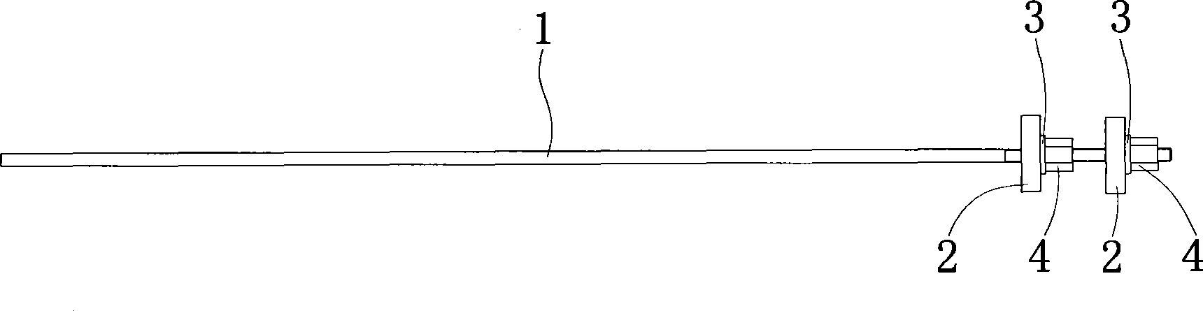
[0027] see figure 1 , the anchor rod has a rod body 1 with external threads on one side, two sets of compression parts arranged on the rod body 1, each set of compression parts includes a tray 2 socketed with the rod body 1, screwed with the rod body 1 and close to the external thread For the nut 4 at the outer end, a washer 3 is set on the rod body 1 corresponding to the space between the tray 2 and the nut 4 in each set of pressing parts, and the length of the external thread is 200mm.

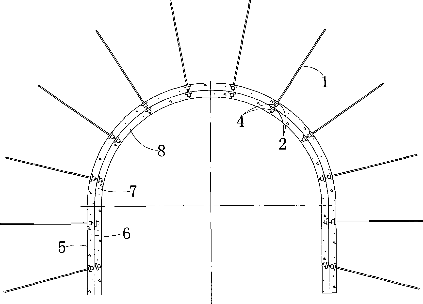
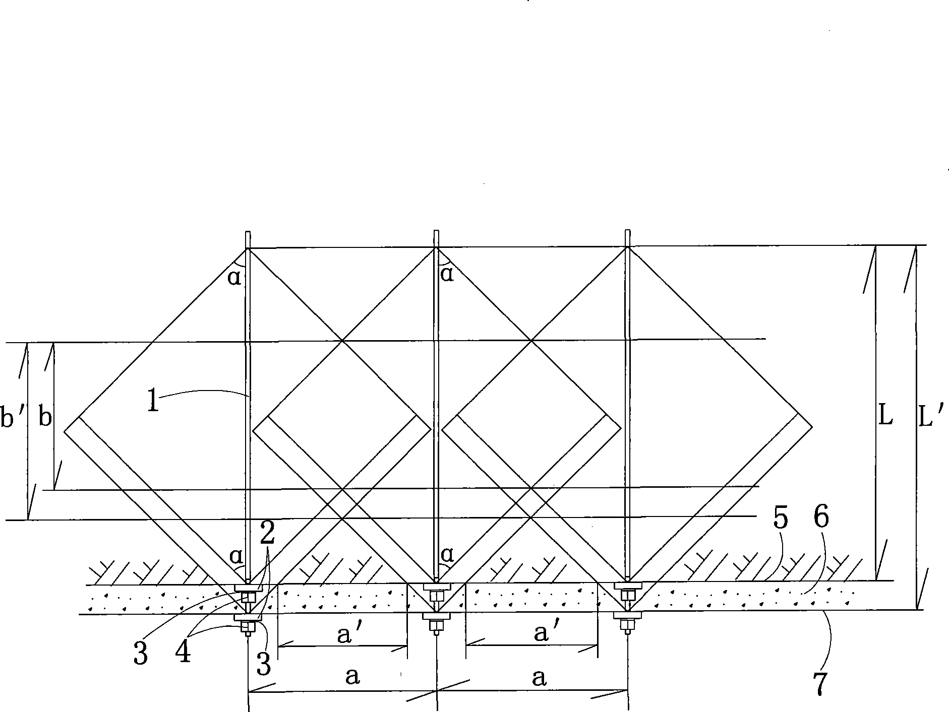
[0028] see figure 2 , the construction method of the bolt, it comprises the following process steps:

[0029] (1) Rock breaking: By blasting or mechanical means, the surrounding rock is broken to the design section size ( figure 2 The surrounding rock is not shown in the figure);

[0030] (2) Anchor hole positioning and hole formation: pre-drill anchor holes...


PUM


Abstract

The invention relates to a composite supporting anchor rod, comprising a rod body with an outside thread arranged at one side and at least two compressing pieces arranged on the rod body, wherein, each compressing piece comprises a tray sheathed with the rod body and a screw nut which is connected with the rod body in a revolving way and is close to the outer end of the outside thread. On the rod body, a washer is sheathed with the part which is corresponding to the part between the tray and the screw nut of each compressing piece. The construction method of the anchor rod is as follows: breaking rock; anchor eye positioning and pore-forming; first net hanging, anchor rod placing, compressing and cement mortar blowing; second net hanging, compressing and cement mortar blowing; according to actual needs of construction, the processes of net hanging, compressing and cement mortar blowing can be repeated, so as to finish plural times of supporting. The anchor rod of the invention features good supporting function, easy manufacturing, convenient installation, low cost and wide application, which is especially applicable to anchor net blowing and supporting of soft rock lanes and solves the problem of premature cracking and damage of concrete spray layer. The construction method of the invention features simple technique, safety and reliability, cost-effectiveness and high efficiency and few employed devices.

Description

technical field [0001] The invention relates to a safety supporting device used in surrounding rock support of underground engineering, in particular to a composite support bolt, and at the same time, the invention also relates to a construction method of the composite support bolt. Background technique [0002] With the development of economic construction, there are more and more underground excavation projects, such as mines and tunnels. In these projects, the surrounding rock needs to be safely supported to prevent the surrounding rock from loosening and rock blocks from falling. [0003] At present, anchor rods are generally used to support the surrounding rock. The structure of the anchor rod is: it has a rod body with external threads on one side, and a set of compression parts arranged on the rod body. The tray, the nut that is screwed to the rod body and close to the outer end of the external thread. [0004] The control range of anchor bolts to loose surrounding ...

Claims


Application Information

Patent Timeline
Patent Type & Authority Applications(China)
IPC IPC(8): E21D21/00E21D20/00E21D20/02
Inventor 于守东
Owner 于守东
Why Eureka
Try Eureka