Magnetic induction measurement method and apparatus

A magnetic induction intensity and measuring device technology, which is applied in the direction of the magnitude/direction of the magnetic field, and the use of magneto-optical equipment for magnetic field measurement, etc., can solve problems such as difficult drawing, high price, and complex optical signal detection system

Inactive Publication Date: 2009-08-19
UNIV OF ELECTRONICS SCI & TECH OF CHINA
View PDF0 Cites 15 Cited by
  • Summary
  • Abstract
  • Description
  • Claims
  • Application Information

AI Technical Summary

Problems solved by technology

The above-mentioned four kinds of magnetic field measurement methods all have the following two problems: one is that the optical fiber (or fiber grating) material used as a magnetic field prob...

Method used


Image

  • Magnetic induction measurement method and apparatus
  • Magnetic induction measurement method and apparatus
  • Magnetic induction measurement method and apparatus

Examples


specific Embodiment approach 1

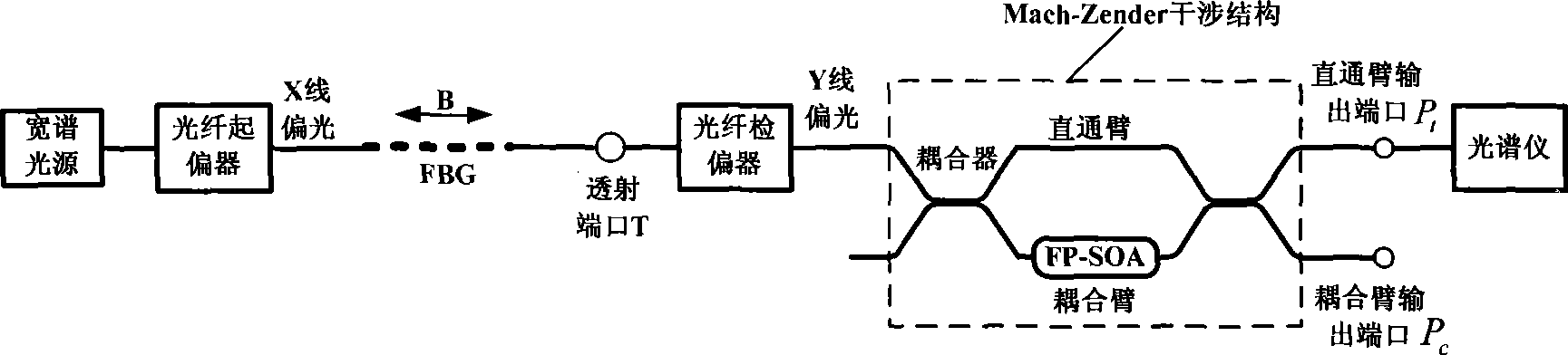
[0018] According to a method for measuring magnetic induction provided by the present invention, a transmission type magnetic induction measuring device, such as image 3 As shown, it includes broadband light source, fiber polarizer, fiber grating (FBG), fiber analyzer, tunable Farpert semiconductor optical amplifier (FP-SOA) and spectrometer. The output light of the broadband light source is incident on the FBG after being polarized by the optical fiber polarizer, and the transmitted light of the FBG under the action of an external magnetic field is analyzed by the optical fiber analyzer perpendicular to the polarization direction of the optical fiber polarizer and converted into mode-converted transmitted light; the mode-converted transmitted light is amplified by an adjustable FP-SOA and then input to a spectrometer.

[0019] In the above technical solution, only one adjustable FP-SOA is used between the polarizer and the spectrometer. In the actual measurement process, in...

specific Embodiment approach 2

[0020] According to a method for measuring magnetic induction provided by the present invention, a reflective magnetic induction measuring device, such as Figure 4 As shown, it includes broadband light source, fiber polarizer, optical circulator, fiber Bragg grating (FBG), fiber analyzer, tunable Faber Semiconductor Optical Amplifier (FP-SOA) and spectrometer. The output light of the broadband light source is polarized by the optical fiber polarizer and is incident into the FBG through the optical circulator. The vertical optical fiber analyzer converts the reflected light into mode conversion after analyzing the polarization; the mode converted reflected light is amplified by the adjustable FP-SOA and then input to the spectrometer.

[0021] In the above technical solution, only one adjustable FP-SOA is used between the polarizer and the spectrometer. In the actual measurement process, in order to increase the optical amplification effect of the FP-SOA so that the spectrome...


PUM


Abstract

A method for measuring magnetic induction intensity and a device thereof belong to the technical field of fiber sensing in electronic information technology and relate to the method for measuring magnetic induction intensity and the device thereof. The invention is based on FBG structure and the magnetic-optic Faraday Effect, and the linear relationship between the relative intensity of FBG mode switching reflection light (or transmitted light) and the magnetic induction intensity B of an externally-applied magnetic field is obtained by measuring the relative intensity of a linearly polarized light with known light intensity and reflected to the mode switching reflection light (or transmitted light) by incidence after FBG under the action of a magnetic filed with known magnetic induction intensity B; and then according to the obtained linear relationship, the magnitude of the magnetic induction intensity B of the magnetic field to be measured can be determined by measuring the relative intensity of the linearly polarized light with known light intensity and reflected to the mode switching reflection light (or transmitted light) by incidence after FBG under the action of the magnetic filed with the magnetic induction intensity B to be measured. The invention has the advantages of high measuring precision, simple use and low cost, and the invention is especially suitable for measuring the size of the magnetic field in the magnetic pole of an electromagnet and for measuring the magnetic field which is generated by high-voltage current.

Description

technical field [0001] The invention belongs to the technical field of optical fiber sensing in electronic information technology, and relates to a method and device for measuring magnetic induction intensity, in particular to a method for detecting the reflection spectrum (or transmission spectrum) of a fiber grating (FBG) under the action of a magnetic field. A method and device for measuring magnetic induction intensity by mode-converting the intensity of light. Background technique [0002] As a sensing component, fiber optic gratings have the advantages of being immune to electromagnetic interference, high sensitivity, wide bandwidth, light weight, small size, corrosion resistance, easy reuse, long-distance telemetry, and being embedded in engineering structures. , and easy to integrate, it can realize multi-point distributed measurement, which overcomes the disadvantages of high cost and low precision of traditional sensor measurement. [0003] At present, the magneti...

Claims


Application Information

Patent Timeline
IPC IPC(8): G01R33/032
Inventor 武保剑程立伟邱昆
Owner UNIV OF ELECTRONICS SCI & TECH OF CHINA
Why Eureka
Try Eureka