Insert for roughing and roughing end mill

A technology of inserts and bodies, applied in the field of insert-detachable roughing end mills, can solve the problems of inconsistent cutting edge rotation trajectories, inconsistent waveform rotation trajectories, inconsistent mutual rotation trajectories, etc., to achieve cutting force, cutting resistance, The effect of surface roughness improvement

Inactive Publication Date: 2009-08-19
MITSUBISHI MATERIALS CORP
View PDF5 Cites 14 Cited by
  • Summary
  • Abstract
  • Description
  • Claims
  • Application Information

AI Technical Summary

Problems solved by technology

[0009] However, as described in Patent Documents 1 and 2, by making the cutting edge of the tip mounted on a part of the chip discharge flutes longer than that of the other inserts, the tips of the cutting edges of the tip of the other chip discharge flutes are mutually In the case of aligning and overlapping, and a part of the cutting edge also overlaps with the next insert of the other chip discharge flutes, for example, as in Patent Document 1, four chip discharge flutes are provided and the cutting edge lengths are alternately installed at the top ends. When inserts with long cutting edges and short inserts are inserted with long cutting edges, the phases of the waveforms of the cutting edges are equal to each other on the tip side where the insert with short cutting edge length overlaps, and the phases of the waveforms of the adjacent inserts in the circumferential direction are equal to each other. The wave-shaped rotation trajectory of the cutting edge of the short blade is inconsistent. On the other hand, on the rear end side between the topmost blade with the short cutting edge length and the next blade, it is necessary to make these blades with a long cutting edge length mutually The cutting edge is not consistent in the rotation path
[0010] Therefore, in this case, as an insert mounted on the top end of the end mill body, an insert with two short cutting edges is required, and the tip side portion of the wave-shaped cutting edge has the same shape, and the rear end side There are two types of inserts with long cutting edge lengths, each of which have different shapes with different rotation trajectories. There are three types of inserts in total, and the manufacturing and management of these inserts require a lot of cost and labor.
In addition, for the second and subsequent inserts of each chip discharge flute, if the positions in the axial direction of the inserts with overlapping cutting edges are aligned in order to facilitate the formation of the mounting seat, such a problem similarly occurs.

Method used


Image

  • Insert for roughing and roughing end mill
  • Insert for roughing and roughing end mill
  • Insert for roughing and roughing end mill

Examples


Embodiment Construction

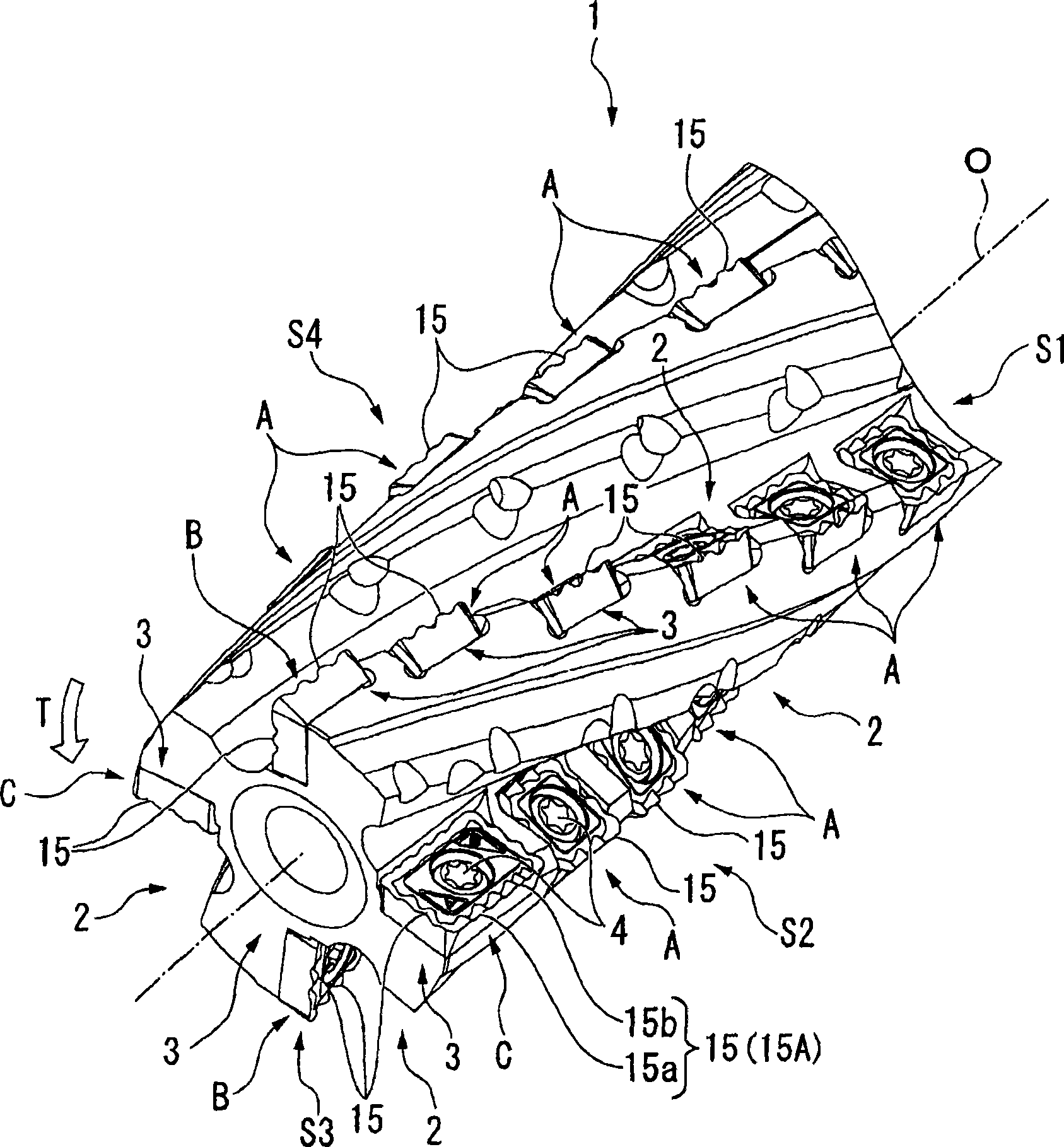
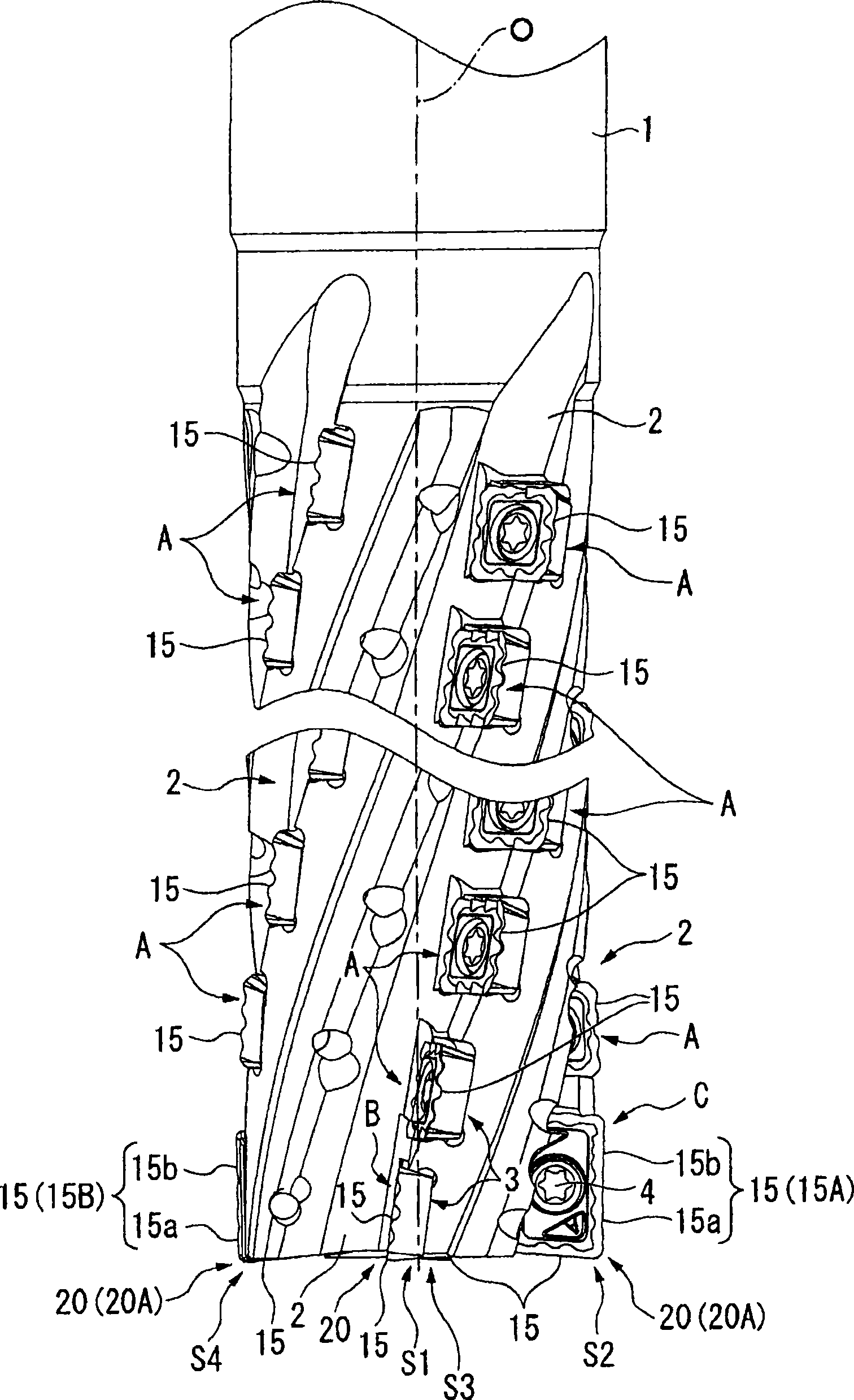
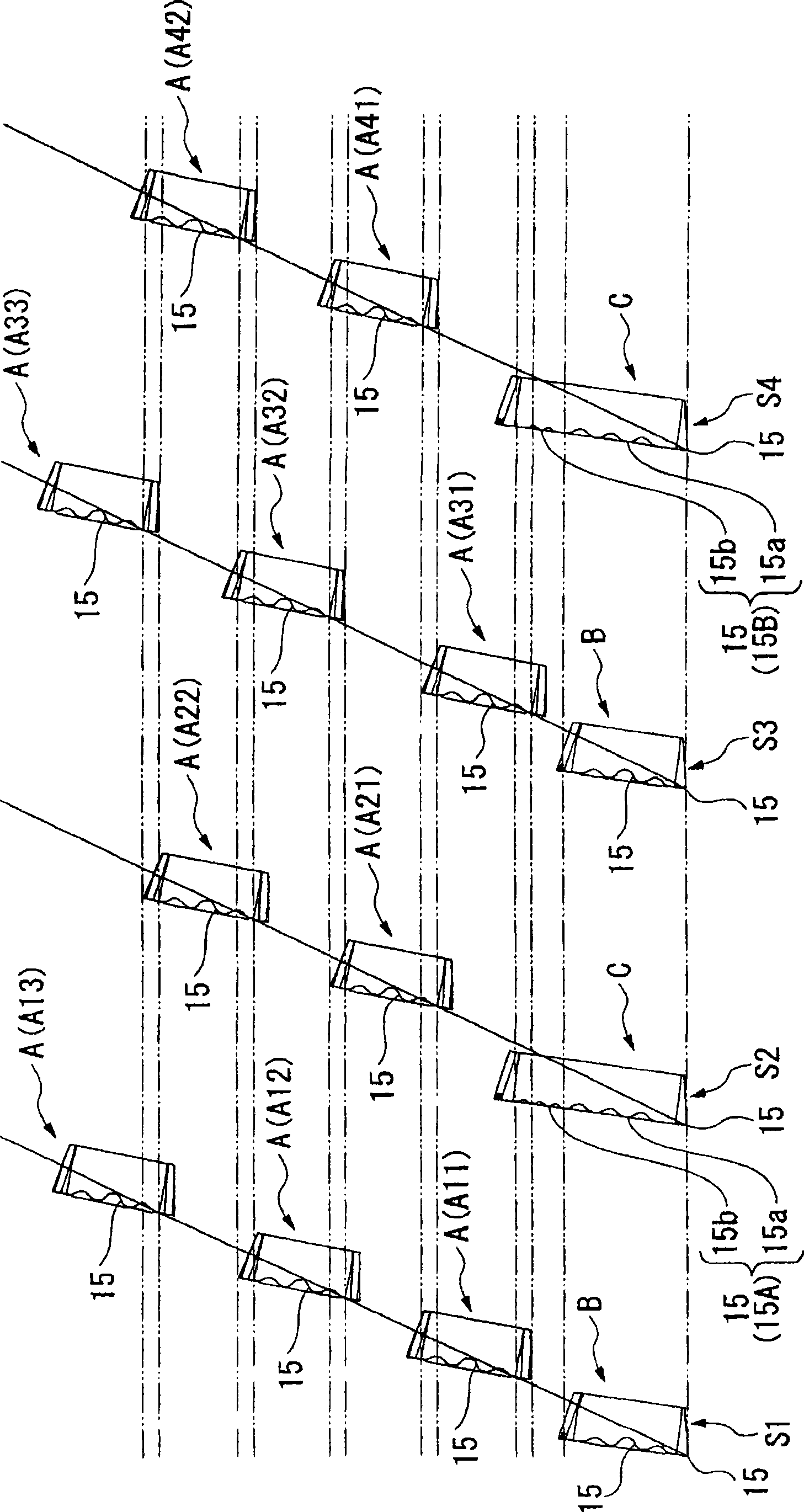
[0057] Figure 1 to Figure 3 One embodiment of the roughing end mill of the present invention is shown. Figure 4 to Figure 8 Blade A shown, Figure 9 to Figure 13 Blade B shown, Figure 14 to Figure 19 The shown insert C is detachably attached to this rough machining end mill, and the insert C is an insert for rough machining according to one embodiment of the present invention. In addition, the other inserts A and B are also inserts for rough machining having wave-shaped cutting edges.

[0058] In the rough machining end mill of this embodiment, the end mill body 1 is formed of steel or the like, and has a substantially cylindrical shape centered on the axis 0. On the outer periphery of the tip part, several lines are formed at equal intervals in the circumferential direction. (Four in this embodiment) Helical chip discharge flutes 2. These chip discharge flutes 2 follow from the front end of the end mill body 1 toward the rear end side in the axis O direction ( figure ...


PUM


Abstract

This roughing insert is provided with an insert body, and a waveform cutting edge which is formed on an intersecting ridge line portion between a rake face and a flank face of the insert body, and which undulates along this intersecting ridge line portion. The waveform cutting edges are formed on the insert body respectively at positions which are rotationally symmetrical at predetermined angularintervals around a reference line of the insert bodies. These waveform cutting edges which are positioned rotationally symmetrically to each other are formed such that, when the insert bodies are rotated by the predetermined angle around the reference line, one or more portions of the waveform cutting edges do not match each other and are mutually asymmetrical.

Description

technical field [0001] The present invention relates to a roughing insert provided with a wave-shaped cutting edge for rough machining a workpiece, and an insert detachable roughing end mill having such a roughing insert attached to the outer periphery of an end mill body . [0002] This application claims the priority of Japanese Patent Application No. 2006-248174 filed on September 13, 2006, and Japanese Patent Application No. 2006-295906 filed on October 31, 2006, and the contents thereof are incorporated herein. Background technique [0003] As such a detachable insert-type roughing end mill, for example, Patent Documents 1 and 2 propose a technology in which a plurality of helical grooves are formed on the outer periphery of a cylindrical tool body and spaced in these helical grooves. The blades in the shape of a quadrangular flat plate are attached with a small gap, and the blades of different helical grooves are arranged at approximately equal intervals so as to comp...

Claims


Application Information

Patent Timeline
Patent Type & Authority Applications(China)
IPC IPC(8): B23C5/10B23C5/20
CPCB23C2200/206B23C2210/66B23C5/207B23C2220/60B23C5/109Y10T407/1942Y10T407/1924Y10T407/192Y10T407/1671Y10T407/195B23C5/202B23C5/20B23C5/10B23C5/22B23B27/16
Inventor 堀池伸和北嶋纯
Owner MITSUBISHI MATERIALS CORP
Why Eureka
Try Eureka