Heat exchange system for producing substrate

The technology of a heat exchange system and a heat exchange device is applied in the field of the heat exchange system of the substrate manufacturing process, which can solve the problems of insufficient market demand, large power consumption of the electric heating wire, factory losses, etc., so as to reduce the production cost and increase the electric heating device. , The effect of device structure improvement

Active Publication Date: 2009-08-26
AMPOC FAR EAST CO LTD
View PDF0 Cites 0 Cited by
  • Summary
  • Abstract
  • Description
  • Claims
  • Application Information

AI Technical Summary

Problems solved by technology

[0005] (1) The heating wire consumes a lot of power, which is very expensive compared to the electricity it costs;
[0006] (2) Because most of the equipment used in the substrate manufacturing process is made of plastic, improper temperature control of the heating wire can easily cause fires and cause unnecessary losses to the factory;
[0007] (3) The heating wire is made of metal, and its service life is short and often needs to be replaced. It is contrary to the increase in the gross profit rate of the current substrate manufacturing process, and it does not meet the needs of the market.
[0008] In view of the defects of the electric heating device in the above-mentioned existing substrate manufacturing process, and the uneconomical use of the electric heating wire as the heating gas or liquid in the conventional substrate manufacturing process, the inventor is based on years of rich practical experience in the design and manufacture of such products and professional knowledge, and with the application of academic theory, actively research and innovate in order to create a new heat exchange system for substrate manufacturing process, which can improve the general existing electric heating devices in substrate manufacturing process and make it more practical

Method used


Image

  • Heat exchange system for producing substrate
  • Heat exchange system for producing substrate
  • Heat exchange system for producing substrate

Examples


Embodiment Construction

[0033] In order to further explain the technical means and effects of the present invention to achieve the intended purpose of the invention, the specific implementation, structure, Features and their functions are described in detail below. For convenience of description, in the following embodiments, the same elements are denoted by the same numbers.

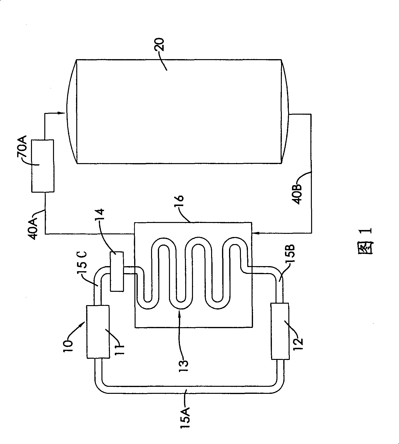
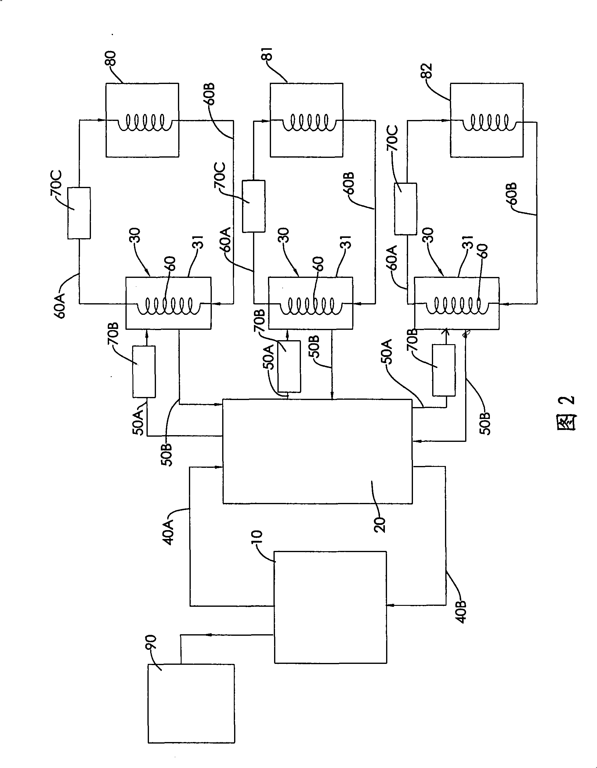
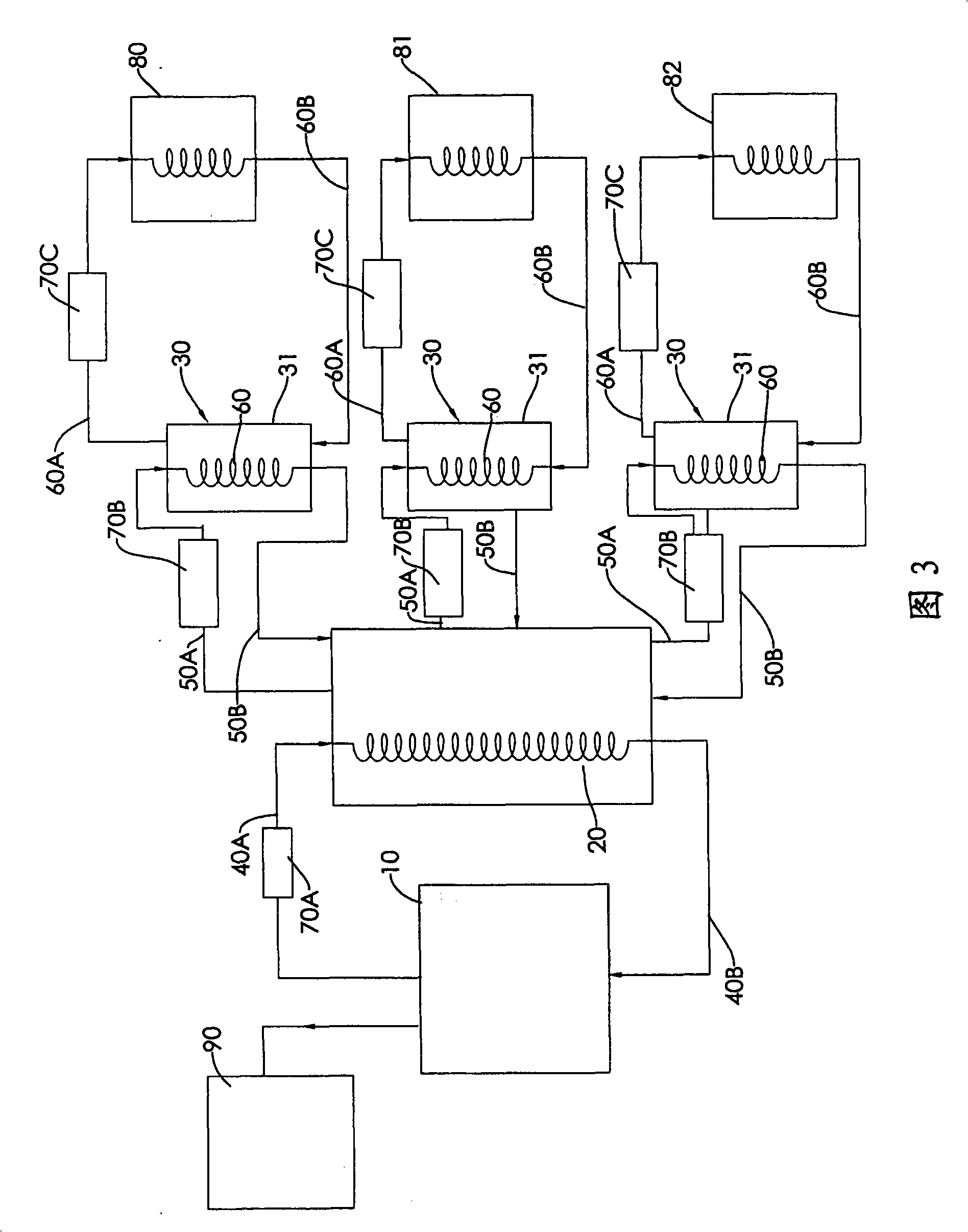
[0034] Please refer to figure 1 and figure 2 , is an embodiment of a heat exchange system of the present invention, consisting of a heat pump device 10, a heat collecting device 20, more than one heat exchange device 30, more than two connecting pipes 40A and 40B, and more than two distribution pipes 50A and 50B and more than one delivery pipe 60.

[0035] This heat pump device 10 is made up of an evaporator 11, a compressor 12, a condenser 13, an expansion valve 14 and a plurality of through pipes 15A, 15B, 15C, and the evaporator 11 is connected to the Between the expansion valve 14 and the compressor 12, and the conden...


PUM


Abstract

The invention relates to a heat exchange system for producing a substrate. The heat exchange system mainly comprises a heat pump device, more than one heat exchange device, a heat collection device arranged between the heat pump device and the heat exchange devices, more than two connecting pipes connected with the heat pump device and the heat collection device, more than two distributing pipes connected with the heat collection device and the heat exchange devices and more than one conveying pipe connected with the heat exchange devices. In the heat exchange system, the heat pump device absorbs heat energy to generate a heat source, and the heat source is collected in the heat collection device and then conveyed to all heat exchange devices by the distributing pipes, so that the heat exchange devices realize the heat exchange of the liquor or gas used in the process of producing the substrate by using the external heat energy to increase the temperature, and the production cost is also lowered.

Description

technical field [0001] The invention relates to a heat exchange system, in particular to a heat exchange system used for substrate manufacturing process. Background technique [0002] Nowadays, in order to increase the output value and increase the gross profit, many factories try to reduce the production cost of the product process to increase the competitiveness in the market. [0003] This is also true for the substrate manufacturing process in the electronics industry. In the substrate manufacturing process, whether it is developing, etching or drying, each process needs to use the heat generated by the electric heating device to dry (such as gas) or chemical liquid. (such as etching solution) to heat the surface of the circuit board or glass substrate to successfully complete the circuit, to avoid the reaction of the substrate surface with the chemical solution or incomplete drying during the development, etching or drying of the substrate. The circuit formed on the su...

Claims


Application Information

Patent Timeline
Patent Type & Authority Applications(China)
IPC IPC(8): F28D7/08F25B30/02H05K3/00
Inventor 苏胜义乔鸿培
Owner AMPOC FAR EAST CO LTD
Why Eureka
Try Eureka