Injection device for die casting machine

A technology of injection device and die-casting machine, which is applied in the field of injection device, can solve problems such as poor maintainability and working environment, miniaturization, light weight limitation, and larger motor size, so as to prevent improper operation and Effects of power loss and motor size reduction

Inactive Publication Date: 2009-08-26
UBE MASCH CORP LTD
View PDF9 Cites 19 Cited by
  • Summary
  • Abstract
  • Description
  • Claims
  • Application Information

AI Technical Summary

Problems solved by technology

[0009] Although a hybrid injection device has been proposed as an injection device for a die-casting machine, in the case of a type in which the injection pressure is boosted electrically and the pressure is maintained after the boost, there are the following problems: When maintaining the voltage, in order to maintain the motor with the highest torque, a large current needs to flow, resulting in a large power loss; and the size of the motor becomes larger
The problem with this is that it has to do with the logic valve
[0032] In addition, although there are other proposals for injection devices (for example, refer to Patent Documents 4 and 5), the devices become larger, the maintainability and working environment are not very good, and there are certain constraints in terms of miniaturization and weight reduction. degree of limitation, etc., there is room for improvement

Method used


Image

  • Injection device for die casting machine
  • Injection device for die casting machine
  • Injection device for die casting machine

Examples


no. 2 approach

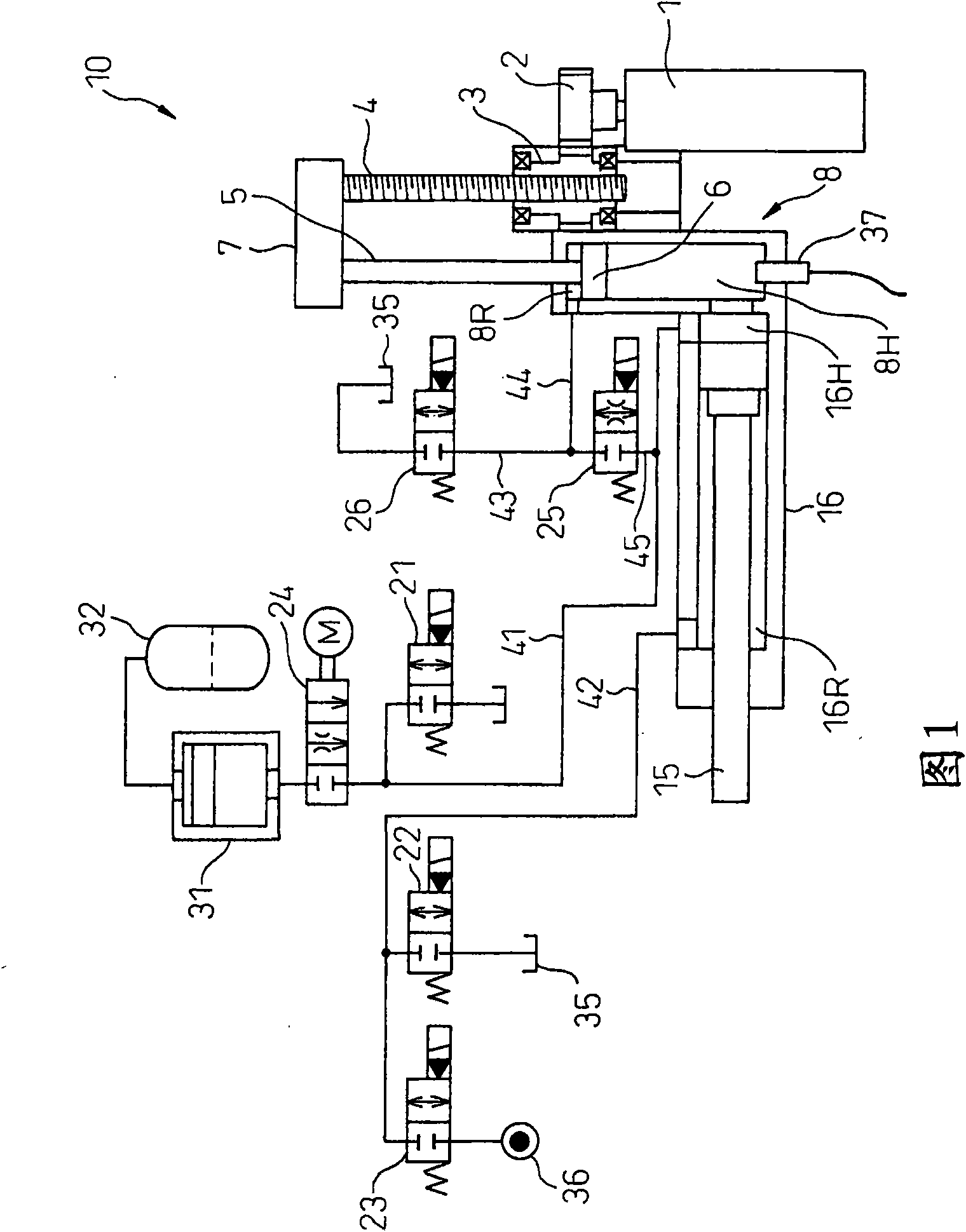
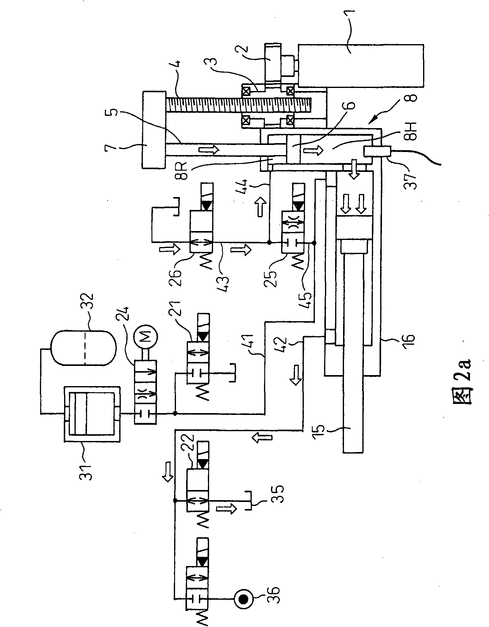
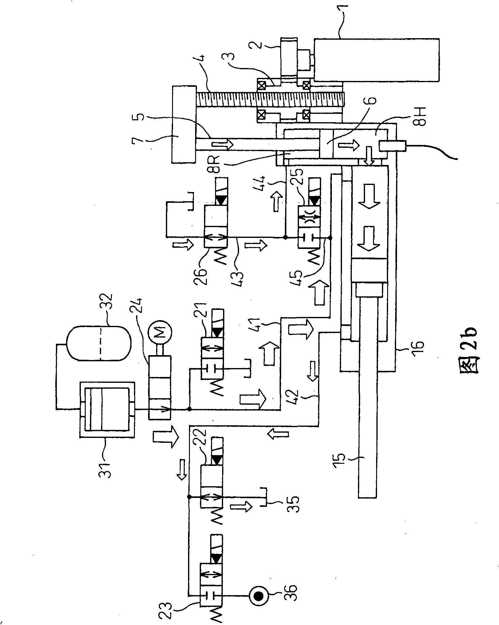
[0135] Hereinafter, an injection device 100 for a die casting machine according to a second embodiment of the present invention will be described. Figure 7 as well as Figure 8a ~ 8g An injection device 100 for a die casting machine according to a second embodiment of the present invention is shown, Figure 7 It is an explanatory diagram showing a schematic configuration of a hydraulic circuit of a second embodiment of an injection device for a die-casting machine, Figure 8a ~ Figure 8g It is an explanatory diagram showing the state of the hydraulic circuit in various working steps of the die casting machine. as with figure 1 , Figure 2a ~ Figure 2f The elements of the first embodiment shown are partially the same or identical Figure 7 as well as Figure 8a ~ Figure 8g The element parts of , are designated by the same reference numerals.

[0136] In the first embodiment, there is no description about the leakage of pressure oil from the piston accumulator 31 for inj...


PUM


Abstract

A hybrid injection device for a die casting machine, in which a large electric power loss is prevented from occurring by avoiding a large current during pressurizing and holding operation and in which the size of a motor is reduced. The injection device has an injection cylinder (16) for receiving an injection piston (15) for injecting a molten metal into a mold and an electric booster (8) operating with a hydraulic cylinder. A head chamber (8H) of an electric booster is fluidically communicated with the head chamber (16H) of the injection cylinder. The head chamber (8H) linearly moves a booster piston rod (5) received in the electric booster (8) to push and move the injection piston, performing injection molding. Because a stop valve (25) is installed in a pipe interconnecting the head chamber (16H) of the injection cylinder and the rod chamber (8R) of the booster (8), the injection device can produce pressure by the head area of the electric booster during the boosting and produce pressure by the rod area thereof during pressurizing and holding operation.

Description

[0001] Cross-references to related applications [0002] The present invention is based on Japanese Patent Application No. 2006-254002 on September 20, 2006, Japanese Special Application No. 2006-324000 on November 30, 2006, and Japanese Patent Application No. 2007-143347 on May 30, 2007. The content of has been written as a reference in this specification and is continued in this application. technical field [0003] The present invention relates to an injection device such as a die-casting machine, and particularly relates to a hybrid injection device. Background technique [0004] In the die casting technology of aluminum alloy, etc., a hydraulic die casting machine in which an injection piston (plunger) is driven by a hydraulic cylinder has conventionally been used. In this type of die casting machine, the injection piston speed and pressure are controlled by adjusting the pressure and flow rate of working oil supplied to the hydraulic cylinder that drives the injection...

Claims


Application Information

Patent Timeline
Patent Type & Authority Applications(China)
IPC IPC(8): B22D17/32
CPCB22D17/2023B22D17/32B22D17/10
Inventor 内田正志平泉一城
Owner UBE MASCH CORP LTD
Why Eureka
Try Eureka