
Device and method for cleaning middle shell cavity of automotive turbine supercharger

A technology for turbochargers and cleaning devices, applied in chemical instruments and methods, cleaning methods and utensils, cleaning methods using liquids, etc., can solve problems such as bearing and shaft damage, low efficiency, and large fluctuations in dynamic values.

Active Publication Date: 2009-09-02
SHANGHAI XIECHANG HUONING MACHINERY MFG
View PDF0 Cites 8 Cited by
  • Summary
  • Abstract
  • Description
  • Claims
  • Application Information

AI Technical Summary

Problems solved by technology

It will inevitably cause the "seizure" between the turbocharger shaft and the shaft sleeve to cause damage to the bearing and shaft, resulting in the paralysis of the overall power system. Control the cleaning degree of the casting in the cavity to ensure the operation and cooling function of the product
[0003] The traditional method of cleaning the inner cavity adopts the method of shock (repetitive), hook picking (manual), and air blowing (compressed air), which has low efficiency, large fluctuations in dynamic values, and poor actual effect
Since the middle shell is placed in an important part of the engine to increase the internal energy, its quality will directly affect the quality of the whole machine, and even the safety performance of the whole vehicle. How to grasp the cleaning degree index and implement strict operating methods during the cleaning process, In order to ensure the pass rate of products, the traditional manual visual inspection and manual operation methods are no longer applicable

Method used

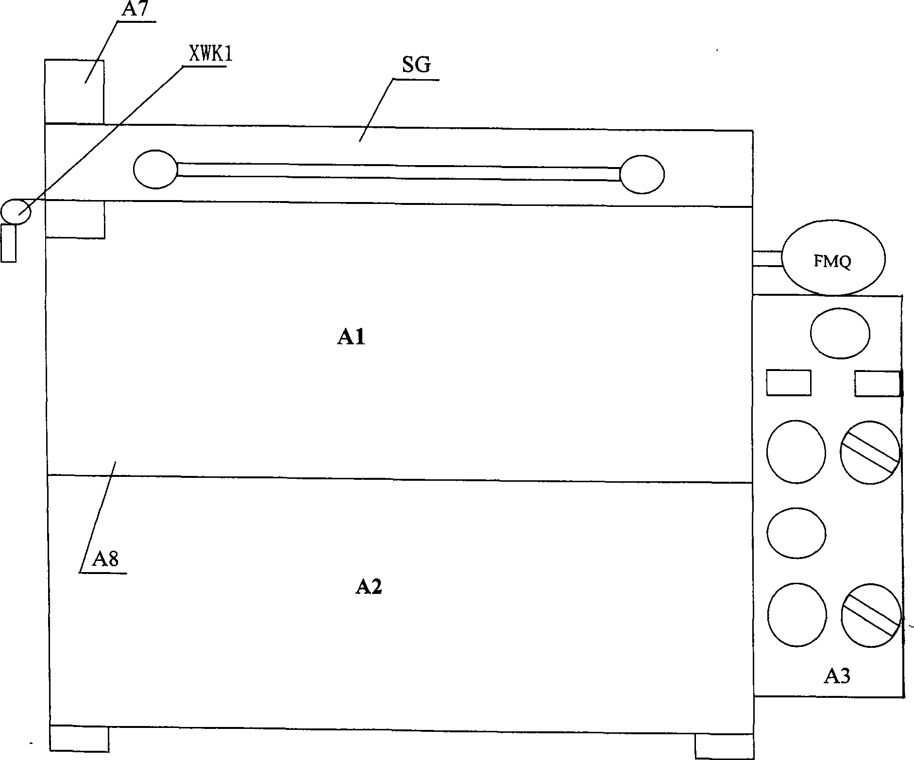
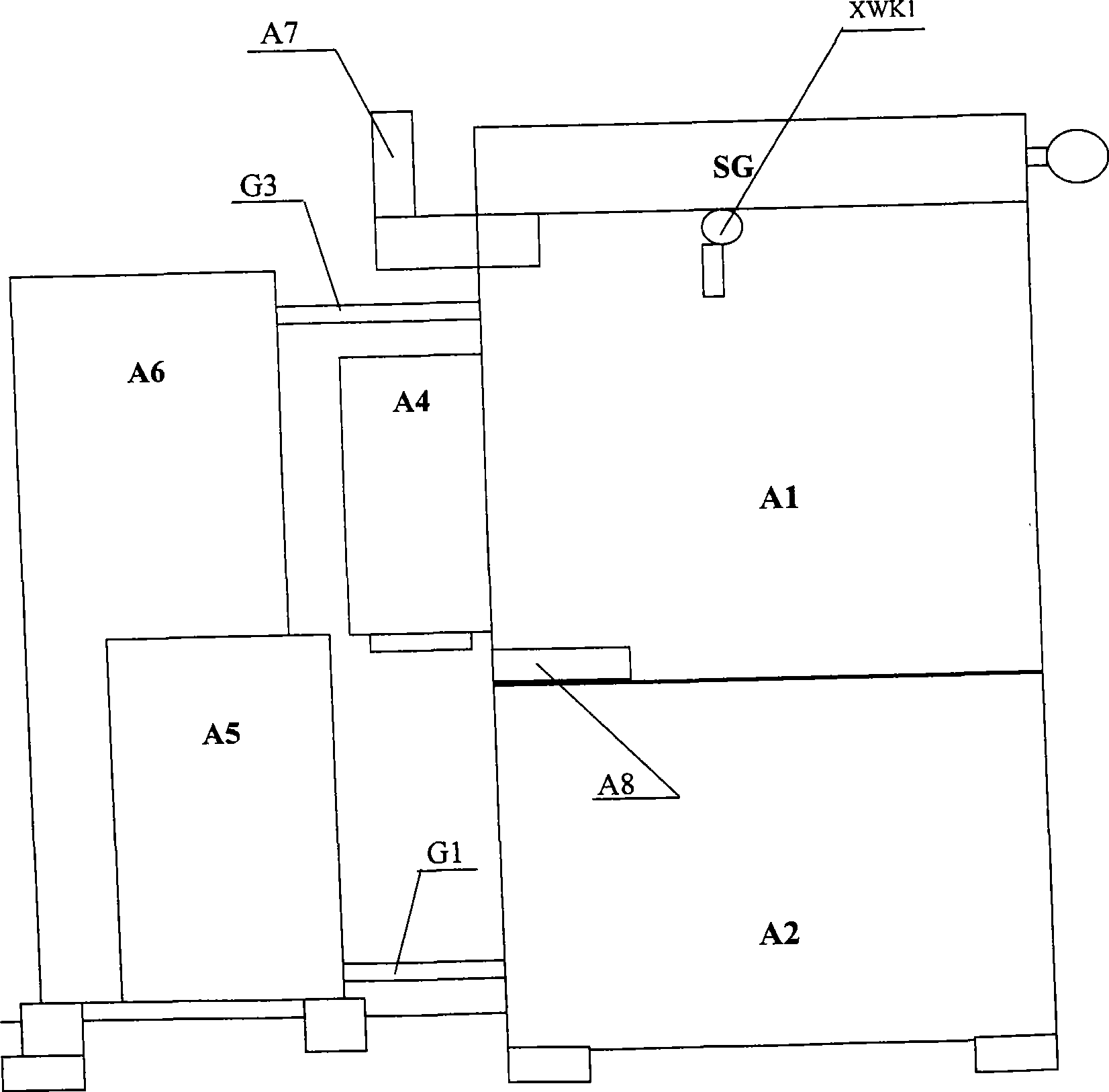
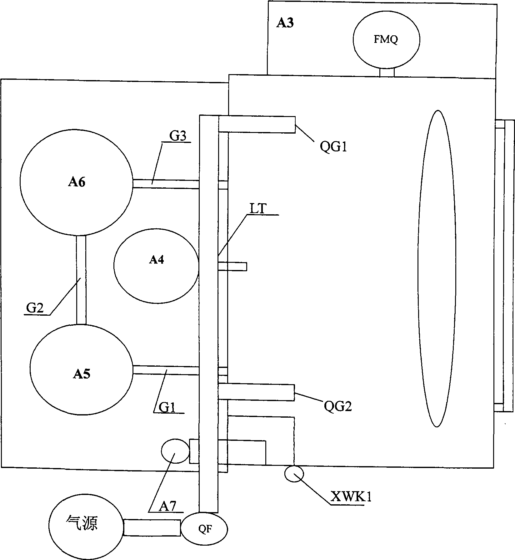

Image

  • Device and method for cleaning middle shell cavity of automotive turbine supercharger
  • Device and method for cleaning middle shell cavity of automotive turbine supercharger
  • Device and method for cleaning middle shell cavity of automotive turbine supercharger

Examples


Embodiment

[0023] Such as Figure 1 to Figure 3 As shown, it is a kind of automobile turbocharger intermediate housing cavity cleaning device provided by the present invention, the exhaust port A7 is arranged on the side of the cleaning chamber A1, the end of the exhaust port A7 is placed outside the cleaning chamber A1, and the cleaning The upper end of the chamber A1 is the chamber cover SG, the left and right pressure springs are connected between the cleaning chamber A1 and the chamber cover SG, a limit switch XWK1 is set on the left side, the automatic mode control box A3 is parallel to the upper right side of the cleaning chamber A1, a vertical multi-stage high-pressure pump A5 is placed on the left rear side of the cleaning room A1, the rotating motor A4 is installed at the rear center of the cleaning room A1, the filter A6 is installed on the right rear side of the cleaning room A1, and the rotary disc motor A4 is connected to the mesh turntable WZP in the cleaning room through th...


PUM


Abstract

The invention provides a device and a method for cleaning a middle shell cavity of an automotive turbine supercharger. The invention adopts the technical proposal that the device comprises a cleaning room and is characterized in that a netlike turntable is arranged in the cleaning room, the periphery of the netlike turntable is provided with at least one seat, a first branch pipe on a first pipeline is extended into the cleaning room and connected with a high-pressure oil distributing valve, at least one second branch pipe on the first pipeline is extended into the cleaning room, an electric control air valve is connected with an air pipe, and the end parts of the air pipe are extended into the cleaning room and arranged on the upper part and the lower part of the netlike turntable respectively. The method comprises: putting a middle shell of the automotive turbine supercharger into the cleaning room, then cleaning a cavity of the middle shell by using the high-pressure oil distributing valve, and cleaning the outer surface of the middle shell by using the second branch pipe and the air pipe. The device and the method for cleaning the middle shell cavity of the automotive turbine supercharger have the advantage that the device and the method can achieve full-automatic cleaning.

Description

technical field [0001] The invention relates to a device and a method for cleaning the inner cavity of an intermediate casing of an automobile turbocharger. Background technique [0002] The automobile turbocharger is installed on the intake and exhaust branch pipes of the engine to make up for the inherent deficiency of the naturally aspirated engine, so that the output power of the engine can be increased by 10% without changing the working volume of the cylinder. Therefore, this supercharging technology is used to improve the output power of the engine, so as to realize the high performance of the car. However, its work is at high temperature; under the condition of high pressure and high speed operation, its working environment is very harsh, and the work requirements are relatively harsh, so it has high requirements for technical processing and cleaning methods. The difficulty is that the total number of particles scattered in the inner cavity of the middle shell is &l...

Claims


Application Information

Patent Timeline
Patent Type & Authority Applications(China)
IPC IPC(8): B08B3/02B08B3/08
Inventor 刘希丕田先民
Owner SHANGHAI XIECHANG HUONING MACHINERY MFG
Learn More