Fan motor

A technology of electric motors and fans, which is applied in the direction of electric components, machines/engines, liquid fuel engines, etc. It can solve the problems of insufficient heat dissipation, unreliable air cooling efficiency, and limit of air inflow, so as to achieve high heat dissipation characteristics and increase the degree of freedom , Improve the effect of heat dissipation characteristics

Inactive Publication Date: 2009-09-02
SANKYO SEIKI MFG CO LTD +1
View PDF1 Cites 10 Cited by
  • Summary
  • Abstract
  • Description
  • Claims
  • Application Information

AI Technical Summary

Problems solved by technology

For example, in the axial flow fan motor described in Patent Document 1, self-cooling is performed by the air flowing in from the opening as described above, but there is also a limit to the inflow amount of the air flowing in from the opening, and the effect above a certain air cooling efficiency cannot be expected.
In addition, although there is a demand to reduce the number of fan motors used in servers, for example, when actually reducing the number of fan motors used, the speed of the fan motor has to be increased. Once the speed is increased, the heat generated from the fan motor will be reduced. etc. resulting in insufficient heat dissipation

Method used


Image

  • Fan motor
  • Fan motor
  • Fan motor

Examples


Embodiment Construction

[0056] Hereinafter, the best mode for carrying out the present invention will be described with reference to the drawings.

[0057] [Mechanical structure]

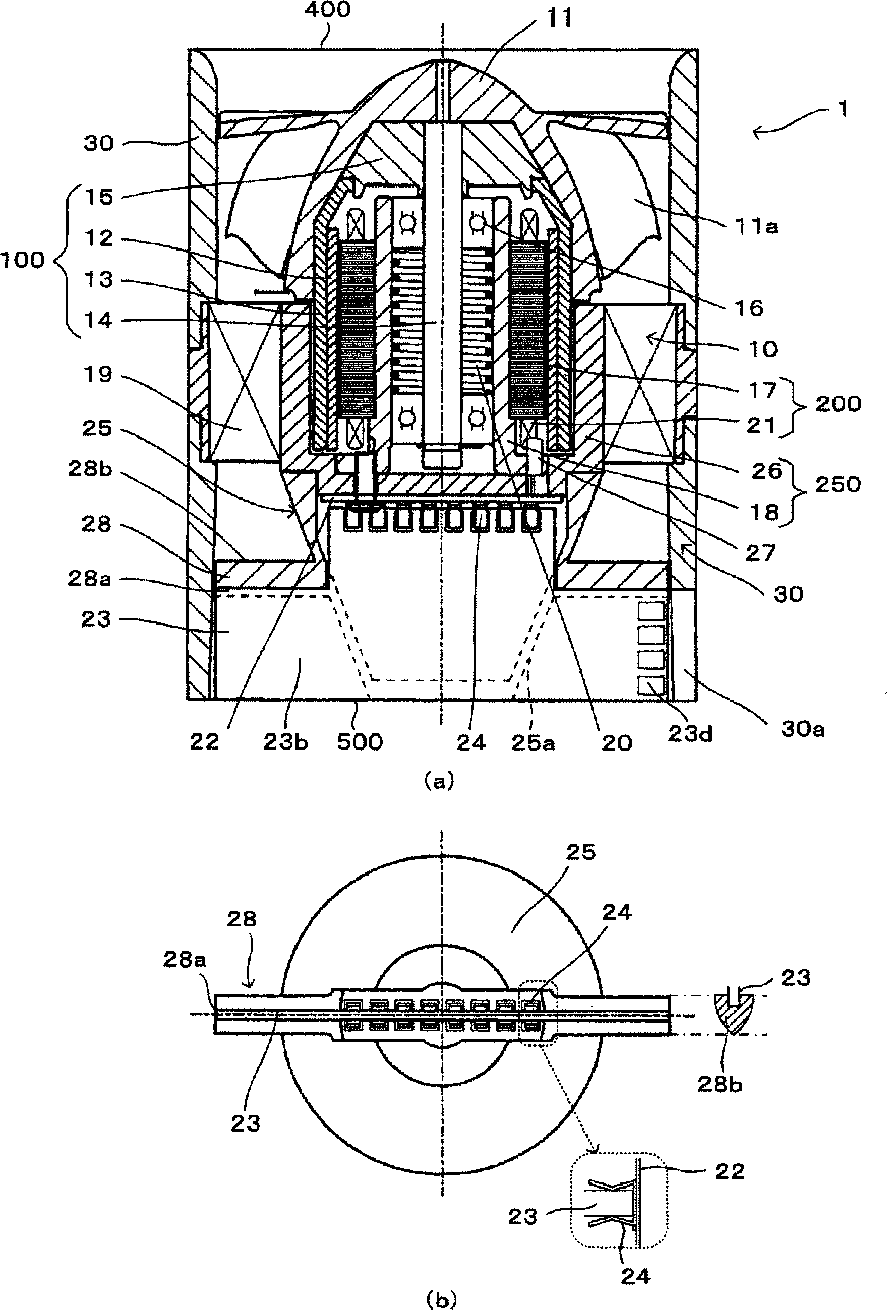
[0058] figure 1 It is a figure which shows the mechanical structure of the fan motor 1 which concerns on embodiment of this invention. in particular, figure 1 (a) is a longitudinal sectional view of the fan motor 1, figure 1 (b) is viewed from the bottom of the figure figure 1 (a) A diagram showing the fan motor 1 (however, the frame is not shown).

[0059] figure 1 The fan motor 1 shown in (a) includes: a fan case 30 as a hollow cylindrical frame having an air inlet 400 and an air outlet 500 , a stator 200 including a drive coil 21 , and a stator support portion for supporting the stator 200 26. The rotor 100 rotatably pivotally supported by the stator support portion 26, the magnet 12 arranged on the rotor 100 in a form opposite to the driving coil 21, and the magnet 12 arranged on the outer peripheral side of the ...


PUM


Abstract

A fan motor having a stator supporting portion (26) for supporting a stator with a drive coil (21), a rotor rotatably supported by a rotating center shaft (rotating shaft (14)) provided at the stator supporting portion (26), a magnet (12) placed on the inner peripheral side of the rotor so as to face the drive coil, a fan (impeller portion (11)) provided on the outer peripheral side of the rotor, a control board (23) having a drive control IC (23a) performing polarity switching control of the drive coil, a hollow tubular frame having a suction opening and a discharge opening, and an installation member (guide blade (19)) for installing the stator supporting portion into the hollow portion of the frame. The control board (23) is placed in the frame so as to be substantially in parallel with the rotating center shaft.

Description

technical field [0001] The present invention relates to a fan motor used as an air cooling device for information equipment such as computers, and more particularly to a fan motor capable of improving heat dissipation characteristics. Background technique [0002] In recent years, with the high performance and high functionality of information equipment, the heat generated by electronic components (for example, CPU, etc.) inside the information equipment is increasing, and the importance of efficient air cooling is increasing. For example, in a server as a host computer, a plurality of CPUs, memories, etc. are arranged to achieve high density and high speed, so a plurality of fan motors are also arranged to improve air cooling efficiency. [0003] In the axial flow fan motor disclosed in Patent Document 1, for example, drive circuit components such as power transistors are arranged in a casing protruding from the casing. An opening is formed in the case through which a part...

Claims


Application Information

Patent Timeline
Patent Type & Authority Applications(China)
IPC IPC(8): H02K5/22F04D25/08F04D29/00F04D29/52F04D29/58H02K5/20H02K7/14H02K11/00H02K21/22
CPCH02K5/225H02K11/0073H02K7/14F04D25/0613F04D25/0633H02K21/22F04D19/002F04D25/068H02K11/33
Inventor 栗田幸信
Owner SANKYO SEIKI MFG CO LTD
Why Eureka
Try Eureka