Eureka AIR delivers breakthrough ideas for toughest innovation challenges, trusted by R&D personnel around the world.

Method and device for recovering after heat of grates of drying grate

A waste heat recovery device and technology for waste heat recovery, which are applied in the field of waste heat recovery of grate beds of chain grate machines, can solve the problems of low efficiency of waste heat utilization methods, reduce ineffective release of cooling heat of grate beds, etc., so as to achieve efficient recovery and utilization and improve waste heat recovery. effect, the effect of improving the utilization rate of heat energy

Inactive Publication Date: 2009-09-09
JIANGSU UNIV
View PDF1 Cites 2 Cited by
  • Summary
  • Abstract
  • Description
  • Claims
  • Application Information

AI Technical Summary

Problems solved by technology

[0005] Without changing the structure of the grate plate, the present invention proposes a method and device for recovering waste heat from the grate bed of the grate machine, which reduces the ineffective release of heat in the cooling of the grate bed, and overcomes the fact that the existing grate machine does not use the waste heat of the grate bed and other devices Low efficiency of waste heat utilization method and other defects, to achieve the purpose of saving energy

Method used


Image

  • Method and device for recovering after heat of grates of drying grate
  • Method and device for recovering after heat of grates of drying grate
  • Method and device for recovering after heat of grates of drying grate

Examples


Embodiment Construction

[0020] According to the structure and size of the B2.8×36m grate machine running chain, the specific implementation instructions will be carried out.

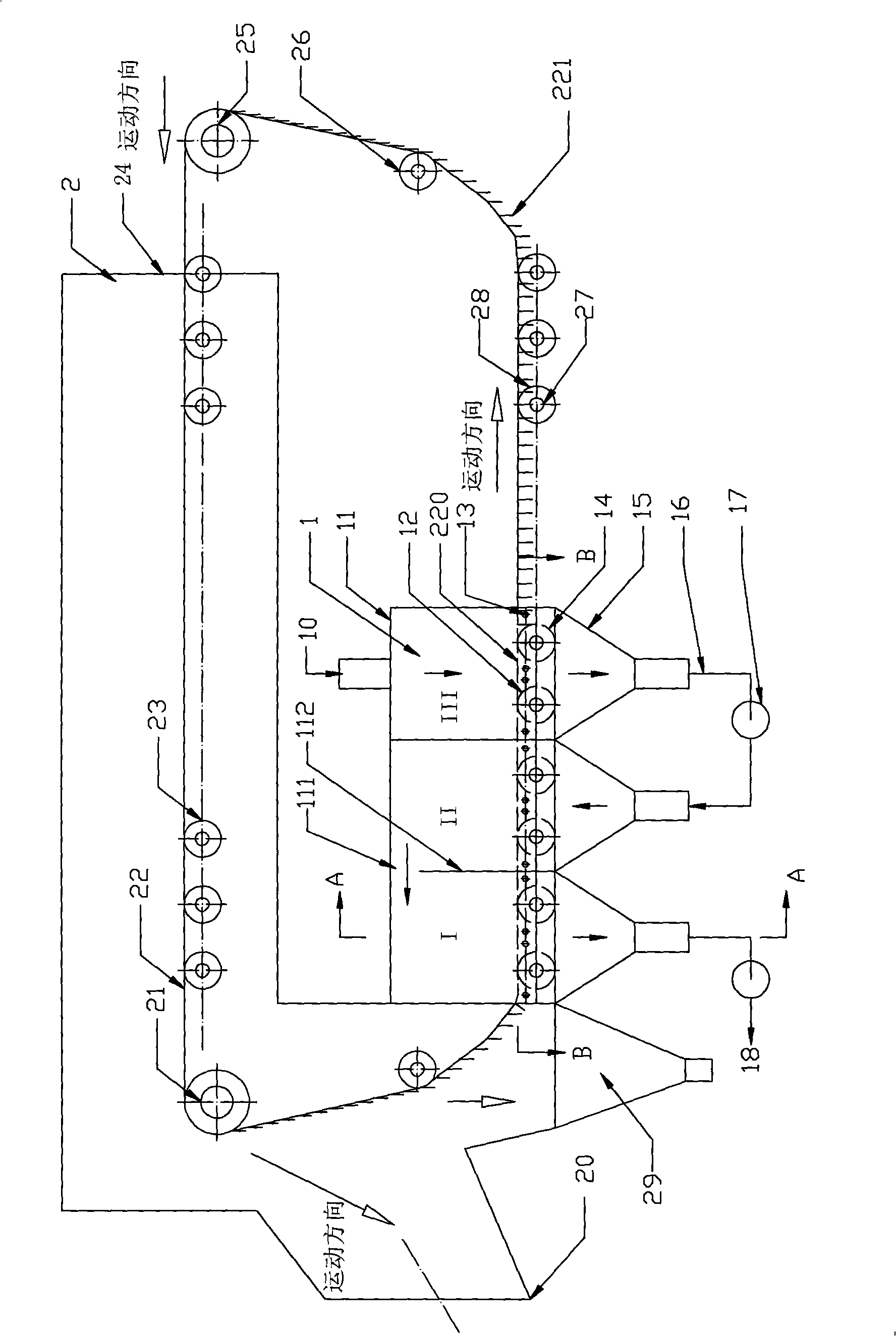
[0021] Such as figure 1 As shown, the grate machine 2 includes: a grate bed 22 for conveying pellets and a grate bed 220 for a return section, a driving sprocket (head sprocket) 21 and a driven sprocket (tail sprocket) 25 for driving the grate bed, and a support grate The upper support roller 23 and the lower support roller 28 of the bed, the grate bed tensioner 26, the support roller shaft 27, the grate machine cover 24, the ash box 29 for collecting dust and the interface part 20 connected with the rotary kiln etc. are composed.

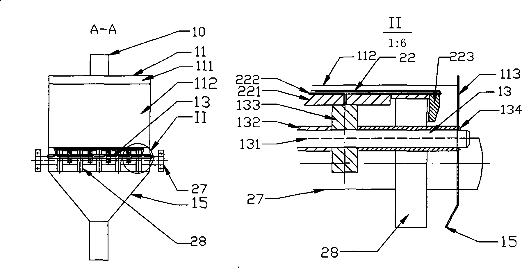
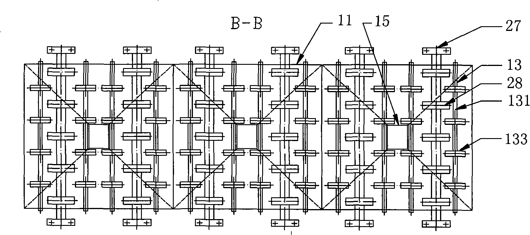
[0022] Such as figure 1 , 2 Shown in and 3, the installation position relationship of the grate bed waste heat recovery device 1 of the present invention is: the return section grate bed 220 installed on the lower part of the grate machine is docked with the ash box 29 and installed in parallel; a...


PUM


Abstract

The invention discloses a method and a device for recovering the after heat of grates of a drying grate and relates to the equipment manufacturing of metallurgical industry. The method and the device are mainly used for a drying grate-rotary kiln-circle-cooling machine process to produce spheric agglomeration. The method adopts the technical scheme that a grate back stroke section on the lower part of the drying grate is additionally provided with at least three grate after heat recovering sections sequentially comprising an after heat recovering section I, an after heat recovering section II, an after heat recovering section III and the like which correspond to the moving direction of the grates, wherein each after heat recovering section is provided with a wind cover above the grate to be cooled and a wind box below the grate so as to ensure that low-temperature hot wind sequentially passes through the wind box and the wind cover from the higher after heat covering section to the lower after heat covering section until reaching the after heat recovering section I, namely, the low-temperature hot wind is subjected to at least three times of heat exchange with the grates; the grates are cooled sequentially; the temperature of the hot wind is raised gradually; and finally the high-temperature hot wind is discharged so as to achieve the high-efficiency recovery of the after heat of the grates, reduce ineffective release of heat during the cooling of the grates, improve the heat energy utilization rate and save the energy resource.

Description

technical field [0001] The invention relates to a method and a device for recovering waste heat from a grate bed of a grate, belonging to the technical field of equipment manufacturing in the metallurgical industry, and is mainly used in the production of pellets by a grate-rotary kiln-ring cooler process. Background technique [0002] Energy is an important material basis for people to produce and survive. With the development of society, energy consumption continues to increase, and people are increasingly aware of the importance of energy issues. In my country's iron and steel smelting industry, energy consumption is high and pollution is high, which is not conducive to my country's sustainable development. The implementation of new technologies for energy conservation and environmental protection is the goal pursued by our country. It is very important for my country to achieve the overall goal of energy conservation and emission reduction in the "Eleventh Five-Year Plan"...

Claims


Application Information

Patent Timeline
Patent Type & Authority Applications(China)
IPC IPC(8): F27D17/00C22B1/20
CPCY02P10/25
Inventor 张西良毛翠云冯爱新李伯全陈沥强张夏蓉张永康杨继昌司乃潮任旭东吴强张锋原瑾
Owner JIANGSU UNIV
Why Eureka
Eureka Blog
Learn More