Oil feeding type auto-tensioner

A tensioner and oil supply technology, applied in the direction of transmission, belt/chain/gear, mechanical equipment, etc., can solve the problems of high chain tension, high processing cost, increased processing cost, etc., and achieve low cost and reduced pressure. small effect

Inactive Publication Date: 2009-09-09
NTN CORP
View PDF2 Cites 5 Cited by
  • Summary
  • Abstract
  • Description
  • Claims
  • Application Information

AI Technical Summary

Problems solved by technology

[0012] However, in the oil supply type automatic tensioner described in Patent Document 1, when the push rod protrudes too much outward due to excessive vibration of the chain, when the engine returns to a low speed, the recovery of the push rod cannot be absorbed, and Cause excessive chain tension and cause breakage, or, cause breakage of the ratchet
In addition, it is necessary to process the rack teeth on the outer peripheral surface of the push rod, which increases the processing cost
[0013] In addition, in the oil supply type automatic tensioner described in Patent Document 2, if the chain tension is too high, since a dynamic load is applied to the push rod, sliding will occur on the contact surface of the dedendum on the pressure side, causing the push rod to slip. Move backwards to prevent excessive tension of the chain, but it takes a lot of time to process the serrated thread, and like the automatic tensioner described in Patent Document 1, it causes a problem of high processing cost
[0014] In addition, in the oil-supply type automatic tensioner described in Patent Document 3, like the automatic tensioner described in Patent Document 1, since the push rod cannot be retracted, there is a concern that the chain tension will become too large. Forming the circumferential groove on the outer periphery of the rod also takes man-hours, resulting in a disadvantage of increased processing costs

Method used


Image

  • Oil feeding type auto-tensioner
  • Oil feeding type auto-tensioner
  • Oil feeding type auto-tensioner

Examples


Embodiment Construction

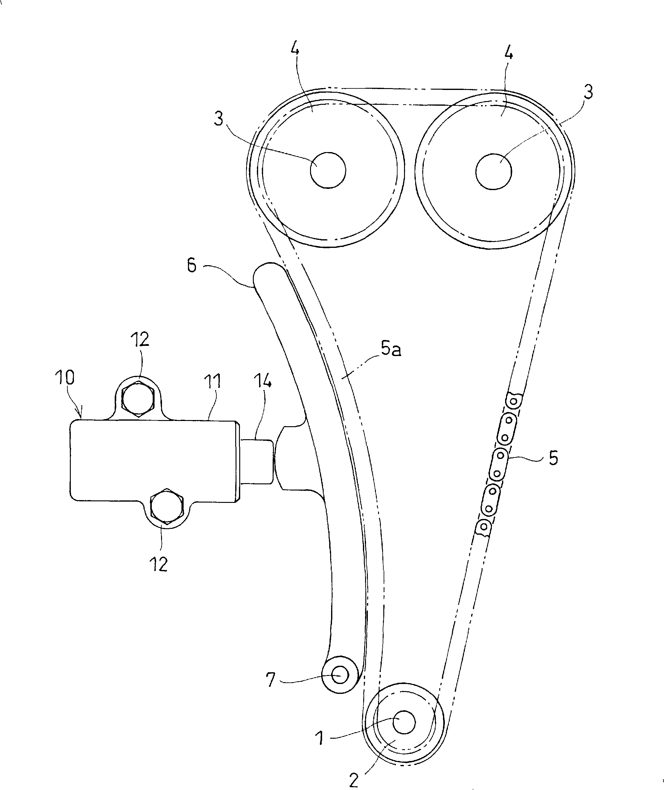
[0039] Hereinafter, embodiments of the present invention will be described with reference to the drawings. figure 1 Indicates the tension adjustment device for the camshaft driving chain. As shown in the figure, a chain 5 is spanned between the sprocket 2 attached to the end of the crankshaft 1 and the sprocket 4 attached to the end of the camshaft 3, and a chain guide 6 is provided on the loose side of the chain 5. .

[0040]The chain guide 6 is swingable around a shaft 7 provided at the lower end thereof. The chain guide 6 is pressed against the chain 5 by the adjustment force of the oil supply type automatic tensioner 10 .

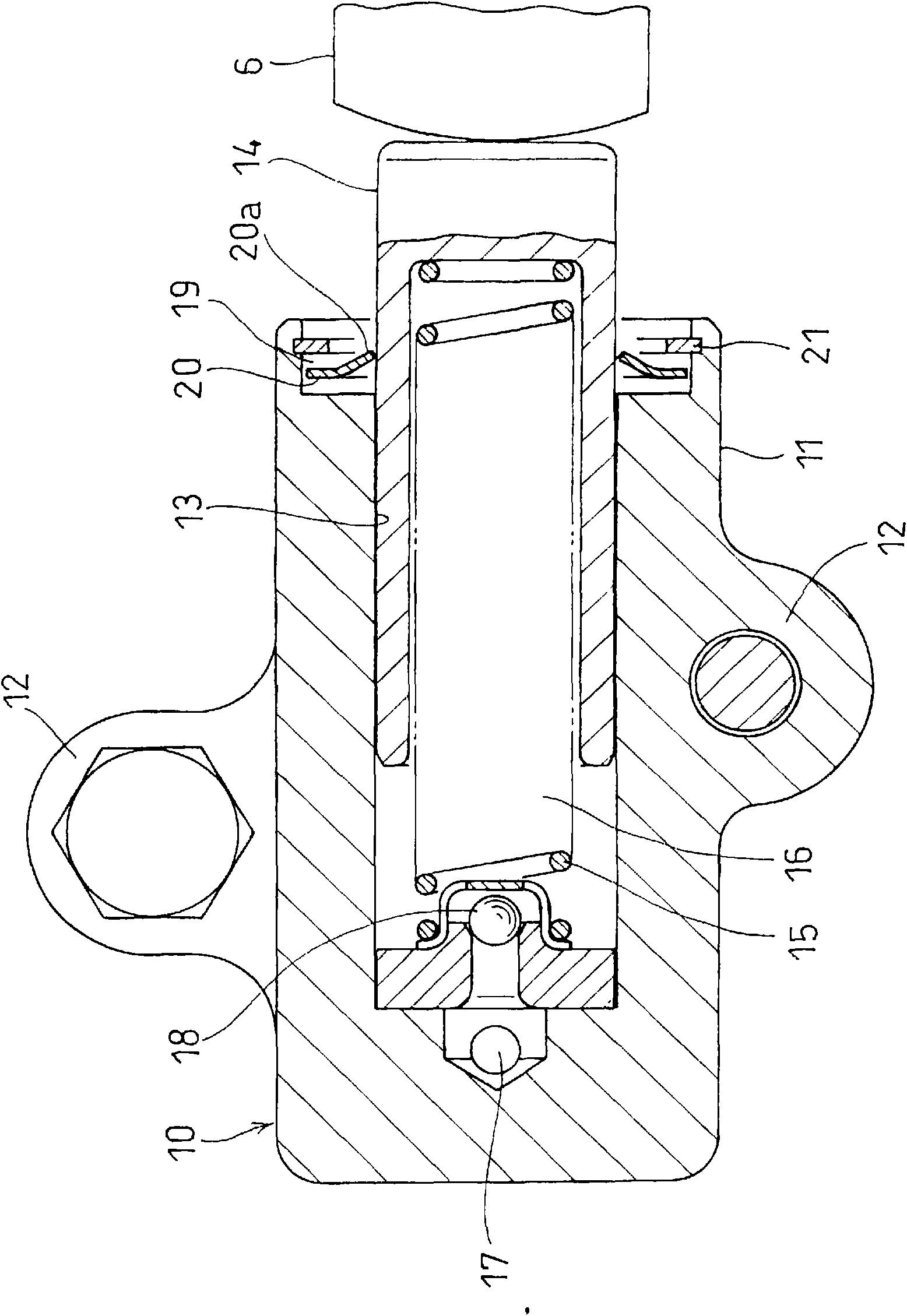
[0041] Such as figure 2 As shown, the oil-supplied automatic tensioner 10 has a housing 11 . Such as figure 1 As shown, the casing 11 has a mounting piece 12 on the outer periphery, and the mounting piece 12 can be fixed on the engine body by bolts. In addition, a cylinder chamber 13 opened on an end surface of the casing is formed in the casing ...


PUM


Abstract

Provided is an oil feeding type auto-tensioner, which is enabled to prevent the working oil in a pressure chamber reliably from being aerated. In a cylinder chamber (13) formed in a housing (11), there are assembled a slidable plunger (14) and a return spring (15) for protruding the plunger (14) outward. In the housing (11), there is formed an oil feeding passage (17), which communicates with a pressure chamber (16) formed in the back of the plunger (14). A check valve (18) is disposed in the working oil exit portion of the oil feeding passage (17). A diametrically large hole portion (19) is formed in the open end portion of the cylinder chamber (13). A braking stop ring (20) is made movable in that diametrically large hole portion (19), and is equipped on its inner circumference with a plurality of engaging members (20a), which are inclined in the projecting direction of the plunger (14) and which engage at their leading internal diameter edges with the outer circumference of the plunger thereby to prevent the backward movement of the plunger. When the plunger (14) is loaded with a pushing force by the chain at an engine stopping time, the braking stop ring (20) is held in the stopped state by the abutment against the closed end face of the diametrically large hole portion (19). By the engagements between the leading end radially inner edges of the engaging members (20a) formed on the inner circumference of the braking stop ring (20) and the outer circumference of the plunger (14), the backward movement of the plunger (14) is blocked to hold the chain in a predetermined tensile state thereby to prevent the plunger (14) from moving largely outward at the restarting time of the engine.

Description

technical field [0001] The present invention relates to an oil supply type automatic tensioner for constantly maintaining the tension of a timing belt or a timing chain for driving a camshaft. Background technique [0002] Generally, in a chain transmission that transmits the rotation of the engine to the camshaft by using a timing belt or a timing chain (hereinafter simply referred to as a chain), an adjustment force of an automatic tensioner is applied to the chain on the slack side of the chain to adjust the tension of the chain. held constant. [0003] As such an automatic tensioner, there is known an automatic tensioner that is equipped with a push rod for pushing the chain that can slide in a cylinder chamber formed in a casing, and a push rod that protrudes the push rod outward. The return spring is provided with an oil supply passage communicating with the pressure chamber formed on the back of the push rod on the housing, and a check valve is provided at the workin...

Claims


Application Information

Patent Timeline
Patent Type & Authority Applications(China)
IPC IPC(8): F16H7/12F16H7/08
CPCF16H2007/0806
Inventor 山本宪
Owner NTN CORP
Why Eureka
Try Eureka