Method and device for controlling flow

A control method and flow rate technology, which is applied in the direction of valve devices, valve lifts, valve details, etc., can solve the problems of small flow capacity, high overall pressure loss at both ends of the valve, and limited control range of dynamic working pressure difference to achieve sealing performance Good, small space occupation, simple structure effect

Inactive Publication Date: 2009-09-16
辽宁华运控制设备制造有限公司
View PDF0 Cites 13 Cited by
  • Summary
  • Abstract
  • Description
  • Claims
  • Application Information

AI Technical Summary

Problems solved by technology

The latest products of dynamic balance electric valves generally adopt the principle of spring mechanical self-reliance, so there are small flow capacity, limited dynamic working pressure difference control range, inflexible application, high starting point of working pressure difference, high overall pressure loss at both ends of the valve, etc. shortcoming

Method used


Image

  • Method and device for controlling flow
  • Method and device for controlling flow
  • Method and device for controlling flow

Examples


Embodiment Construction

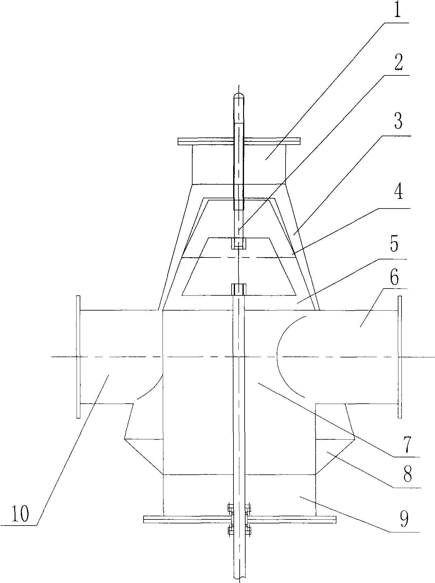
[0030] See figure 1 , figure 2 , a control device for fluid pressure and flow, the device includes an upper cone 3, a lower cone 8, a guide cylinder 4, a conical ring valve core 5, a guide shaft 2, a transmission shaft 7, a fluid inlet 10, and a fluid outlet 6 , top cover 1, bottom cover 9, guide tube 4 is a cylinder structure with upper and lower openings, located in the upper cone 3, and has a certain gap with the inner wall of the upper cone 3; the upper part of the cone ring valve core 5 is provided with a guide shaft 2. There is a transmission shaft 7 at the lower part, and the conical ring valve core 5 is located in the guide tube 4, and there is a certain gap with the inner wall of the guide tube 4; a top cover 1 is provided on the upper part of the upper cone 3, and the lower part of the lower cone 8 A bottom cover 9 is provided; a fluid inlet 10, a gap between the guide tube 4 and the inner wall of the upper cone 3, an upper opening of the guide tube 4, a gap betwee...


PUM


Abstract

The invention relates to a method and a device for controlling flow. The method takes preset flow rate as a constant state, and realizes the adjustment of the flow of a fluid by adjusting the sectional area of a gas channel, and the flow adjustment is in a linear state. A method for adjusting the area of the gas channel is realized by making a conical ring valve core move up and down in a flow guiding cylinder through a controller according to a specified mathematical model and adjusting the change of channel area between the conical ring valve core and the flow guiding cylinder; and the output flow of the fluid is controlled in a real-time mode according to the requirement of process parameters of downstream equipment. The method has accurate metering, fine adjustment function, and no noise. The control device has the advantages of good sealing performance, simple and convenient structure, small occupied space, easy maintenance, high temperature resistance, wear resistance and the like.

Description

technical field [0001] The invention relates to a flow control method and a control device, in particular to a method for adjusting gas flow by adjusting the flow area of ​​the fluid in a state of constant flow velocity of the fluid. Background technique [0002] In the prior art, the flow control of the fluid is based on the premise that the medium passing through the flow channel converts the pressure energy into sound energy or other potential energy to consume the kinetic energy of the fluid. [0003] The commonly used adjustment method is a piston-type fluid control valve. This control valve transmits a pressure differential signal to the flow-limiting pilot valve through the Pitot tube. The flow-limiting pilot valve and the needle valve perform two-way control. The flow-limiting pilot valve adjusts the bolt Adjust, so that the adjusted flow rate is roughly the set value, and the downstream pressure of the main valve is controlled through the adjustment of the pressure ...

Claims


Application Information

Patent Timeline
Patent Type & Authority Applications(China)
IPC IPC(8): F16K1/12F16K27/02F16K1/32
Inventor 代军由胜军
Owner 辽宁华运控制设备制造有限公司
Why Eureka
Try Eureka