
Low current signal amplifier

A signal amplifier and weak current technology, which is applied in the direction of instruments, static indicators, cathode ray tube indicators, etc., can solve the problems of large switching noise, unable to meet the imaging requirements of weak current signals, and affect the function and performance of analog circuits. Effect of clock delay digital switching noise, readout order controllable integration capacitor, effect of reducing the effect of digital switching noise

Inactive Publication Date: 2009-09-16
瑞声声学科技(常州)有限公司 +1
View PDF5 Cites 19 Cited by
  • Summary
  • Abstract
  • Description
  • Claims
  • Application Information

AI Technical Summary

Problems solved by technology

[0005] 1. A large number of digital gate circuits are frequently flipped under the action of the system main clock, which will generate very large switching noise. In the digital-analog hybrid system, these noises will seriously affect the function and performance of the analog circuit
[0006] 2. The integral capacitance of the pixel unit circuit is fixed, which limits the application of some application systems
Therefore, in the case of a strong background signal, the charge storage capacity of the weak current signal amplification circuit is required to be large enough, which requires the integral capacitor to be large enough to collect all the charges. The effect often fails to meet the requirements of the application system; and in the case of a weak background signal, there is little requirement for the charge storage capacity of the circuit, and the required integral capacitor is small. If the integral capacitor is fixed, it will inevitably cause a decrease in system power consumption. increase and decrease in circuit speed, seriously affecting the function and performance of the circuit
[0007] 3. The weak current signal amplifying integrated circuit has only one readout sequence, that is, the positive sequence readout from channel 1 to channel N. The fixed readout order makes the system imaging mode fixed, which cannot meet the specific needs of weak current signal detection and imaging fields. imaging needs

Method used


Image

  • Low current signal amplifier
  • Low current signal amplifier
  • Low current signal amplifier

Examples


Embodiment Construction

[0046] The present invention will be further described below in conjunction with the accompanying drawings.

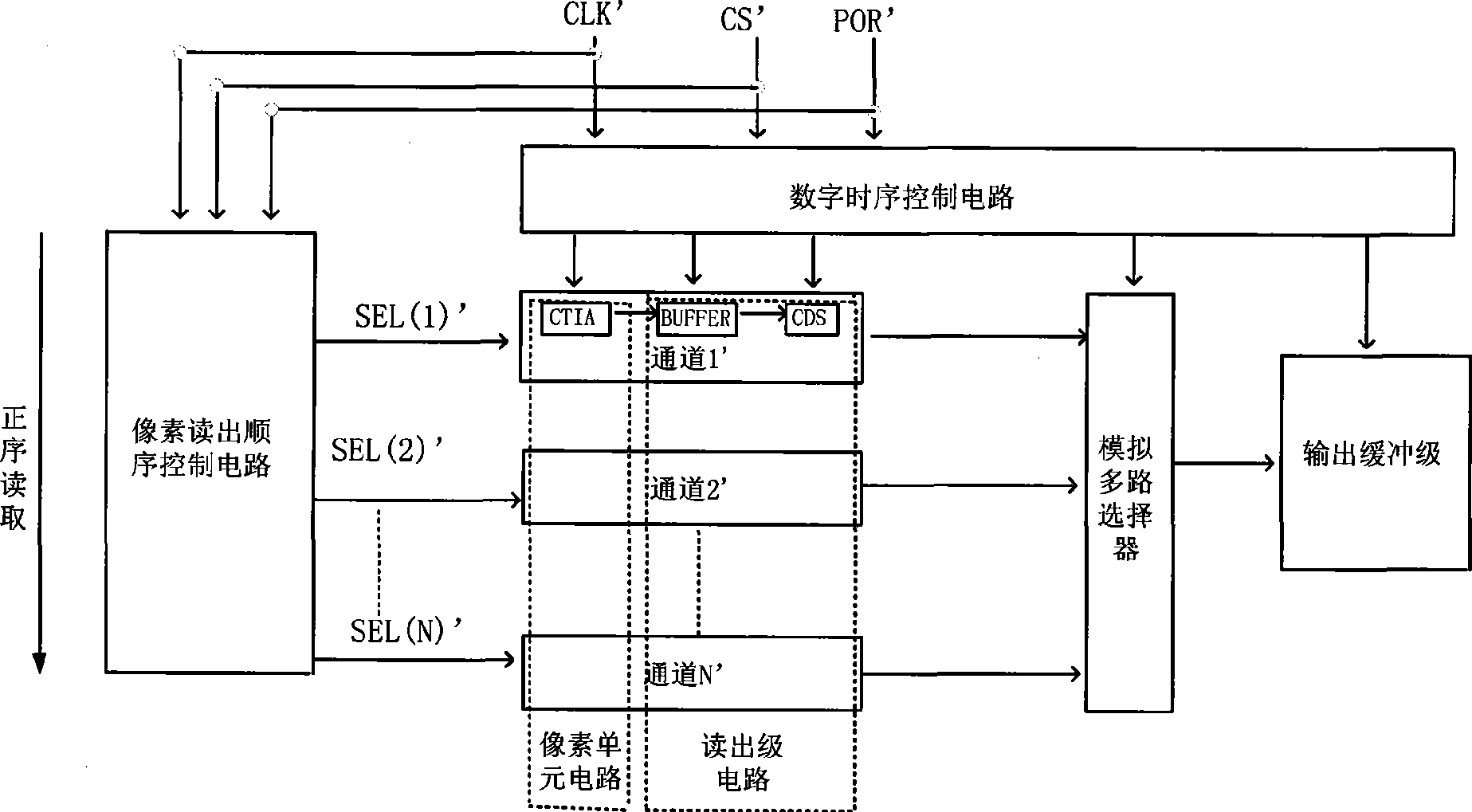
[0047] The weak current signal amplifier provided by the present invention includes a pixel conversion unit for amplifying the weak current signal, converting it into a voltage signal, and outputting the voltage signal; a pixel readout sequence control unit for controlling the pixel conversion unit to output The sequence of the voltage signal; the readout stage unit, reads the voltage signal output from the pixel conversion unit and processes and amplifies it; the analog multiplexer controls the signal that is processed and amplified by the readout stage unit , and output the signal amplified by the processing; the output buffer stage unit is used to process the signal output by the analog multiplexer; the digital timing control unit is used to receive the signal input to the weak current signal amplifier signal, and generate the control signal in the weak current sign...


PUM


Abstract

The invention provides a low current signal amplifier including a pixel converting unit, a pixel read-out sequence control unit, a read-out stage unit, an analog multiplex selector, an output buffer stage unit, a digital time sequence control unit, where an integral reset control signal and said electrical reset control signal are output to the digital time sequence control circuit unit and the pixel read-out sequence control circuit unit respectively; furthermore, the low current signal amplifier includes a clock delay unit, where the master clock signal thereof is output to the pixel read-out sequence control unit and the digital time sequence control unit. According to the invention, a clock delay unit is added to the low current signal amplifier, which avoids the situation of large gate circuits reversed simultaneously, reduces switching noise, and decreases noise effect influenced on the low current signal amplifier.

Description

technical field [0001] The invention relates to a current signal amplifier, in particular to a weak current signal amplifier. Background technique [0002] Detection and imaging systems for weak current signals such as X-rays and infrared rays are being increasingly widely used in non-destructive detection in security inspections, public safety, environmental protection, medical CT scanning, and national economy-related fields. The core is the detection array component. The detection array component is composed of a detector array and a weak current signal amplifying integrated circuit, and the weak current signal amplifying integrated circuit is the main factor affecting the function and performance of the component. The weak current signal amplification integrated circuit is a highly integrated chip that integrates various functions on a semiconductor chip. Its basic function is to realize photoelectric conversion, processing amplification and multiplex transmission of the...

Claims


Application Information

Patent Timeline
IPC IPC(8): G09G5/00
Inventor 杨永刚司鹏飞郭增良林海王晶
Owner 瑞声声学科技(常州)有限公司
Learn More