Traction drive of a rail vehicle for driving and generative braking

A traction drive and generator braking technology, applied in electric braking systems, control systems, motor vehicles, etc., can solve the problems of braking performance, inherent braking characteristic curve without constant braking torque curve of rotational speed, etc. problem, to achieve the effect of simple structure design

Inactive Publication Date: 2009-09-16
KNORR BREMSE SYST FUR SCHIENENFAHRZEUGE GMBH
View PDF1 Cites 7 Cited by
  • Summary
  • Abstract
  • Description
  • Claims
  • Application Information

AI Technical Summary

Problems solved by technology

[0005] Therefore, when utilizing the dynamic braking effect of a permanently excited synchronous motor, the problem arises that the inherent braking characteristic curve does not have a constant braking torque curve with respect to the rotational speed
This means that there is a disadvantage in terms of braking performance compared to today's common technology with adjustable braking force

Method used


Image

  • Traction drive of a rail vehicle for driving and generative braking
  • Traction drive of a rail vehicle for driving and generative braking
  • Traction drive of a rail vehicle for driving and generative braking

Examples


Embodiment Construction

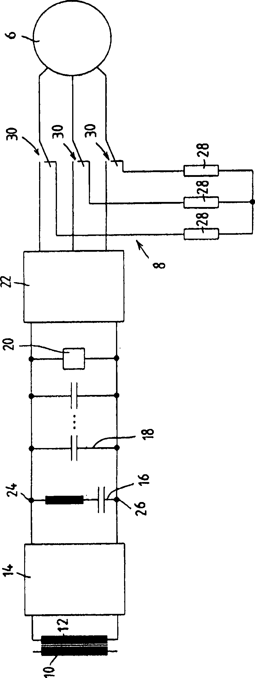
[0020] figure 1 The traction drive system 1 for AC trams (also known as AC rail vehicles) is shown in detail in , where 2 represents a traction transformer, 4 represents a traction converter, and 6 represents a permanent magnet excitation synchronous motor , with 8 representing a braking device. The traction transformer 2 has a primary winding 10 and a plurality of secondary windings 12, only two of which are shown here. The traction converter 4 has two four-quadrant regulators 14 , a snubber circuit 16 , a capacitor battery 18 , an overvoltage protection device 20 and a pulse converter 22 on the machine side. Two four-quadrant regulators 14 are connected in each case to a secondary winding 12 of the traction transformer 2 on the AC voltage side and connected in parallel on the DC voltage side. The absorber circuit 16 , the capacitor battery 18 , the overvoltage protection device 20 and the DC voltage-side input connection of the motor-side pulse converter 22 are connected ...


PUM


Abstract

The invention relates to a traction drive (1) for the driving and generative braking of a rail vehicle or a combination of rail vehicles, a permanent-field synchronous motor (6a, 6b) and a traction current converter (4a, 4b) being respectively associated with at least two axles of the rail vehicle or combination of rail vehicles. The traction current converter (4a, 4b) comprises at least one pulse current converter (22) on the engine side, and the clamps of the permanent-field synchronous motor (6a, 6b) are connected to a change-over switch (30a, 30b) such that the permanent-field synchronous motor (6a, 6b) can be connected to a load circuit (32a, 32b) containing at least one load element (28a, 28b), in order to drive the pulse current converter (22) or for generative braking. According to the invention, the load circuits (32a, 32b) connected to the permanent-field synchronous motors (6a, 6b) for generative braking are designed such that the brake characteristic lines of the permanent-field synchronous motors (6a, 6b) differ in terms of characteristic features such as the position of the maximum of the brake torque according to the rotational speed.

Description

Background technique [0001] The present invention starts from such a traction drive system for driving and regenerative braking (regenerative braking) of a rail vehicle or rail train, wherein at least two axles of the rail vehicle or rail train are each equipped with a Permanent-magnet-excited synchronous motor and a traction converter with at least one pulse converter on the motor side, the permanent-magnet-excited synchronous motor is connected to a changeover switch at its terminals in such a way that the permanent-magnet Exciting synchronous motors can be switched through a pulse converter for drive or a load line containing at least one load element for dynamic braking, as stated in the preamble of claim 1 . [0002] The goal in rail vehicle equipment is ultimately more efficient and lighter drives. As the standard drive equipment, it is currently an asynchronous motor powered by a frequency converter. However, such devices have little potential for improvement in terms...

Claims


Application Information

Patent Timeline
Patent Type & Authority Applications(China)
IPC IPC(8): H02P6/24H02P3/22B60L7/06
CPCB60L2200/26H02P5/74B60L7/08B60L7/06B60L7/22H02P3/22B60L7/003H02P2207/05Y02T10/642B60L2220/14Y02T10/64
Inventor F·黑勒U·弗里森
Owner KNORR BREMSE SYST FUR SCHIENENFAHRZEUGE GMBH
Why Eureka
Try Eureka