Manufacturing method of magnetic grinder and magnetic grinder thereof

A magnetic grinding and manufacturing method technology, which is applied in the direction of machine tools, grinding machines, and manufacturing tools suitable for grinding the edge of workpieces, can solve the problem of reducing the grinding efficiency and effect of magnetic grinding machines, the operation of magnetic grinding machines is not humanized enough, and the increase in Problems such as the difficulty of magnet replacement, to achieve good promotion value, increase the magnetic action area, and the effect of fast speed

Inactive Publication Date: 2009-09-23
HUZHOU XING XING ABRASIVE
View PDF0 Cites 12 Cited by
  • Summary
  • Abstract
  • Description
  • Claims
  • Application Information

AI Technical Summary

Problems solved by technology

[0003] The magnets installed on the tray of the existing magnetic grinding machine are equidistant and symmetrically installed. In this way, in the production process, the magnetic field in the middle position of the symmetrical magnet is often weak, and the middle part is easy to accumulate material, forming dead angles, etc., reducing the grinding of the magnetic grinding machine. The efficiency and effect of machining; the magnets installed on the tray are fixed with screws or pressing sheets, which not only increases the difficulty of replacing the magnets, but also accelerates the magnetic loss of the magnets; at the same time, some magnetic grinding machines are placed in the container or When the workpiece is taken out, the grinding needle is attracted by the magnet, and is affected by the weight of the container, workpiece and grinding needle itself, which often causes violent impact when placed; it is difficult to lift when unloading, which makes the operation of the magnetic grinding machine not humanized enough.

Method used


Image

  • Manufacturing method of magnetic grinder and magnetic grinder thereof
  • Manufacturing method of magnetic grinder and magnetic grinder thereof
  • Manufacturing method of magnetic grinder and magnetic grinder thereof

Examples


Embodiment

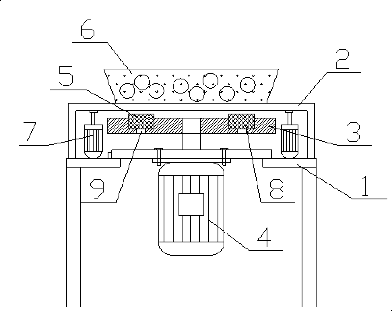
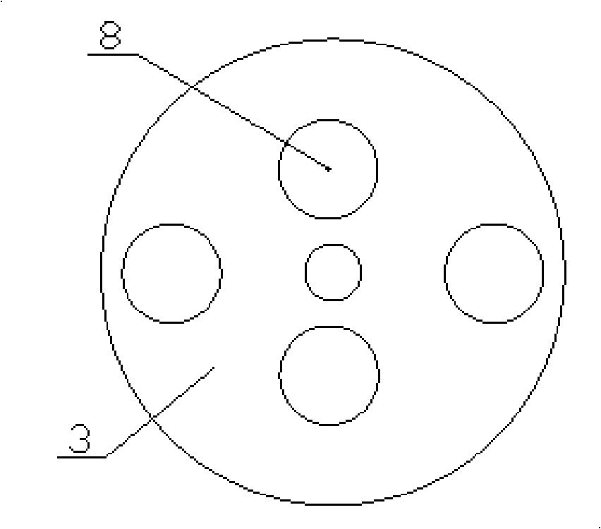
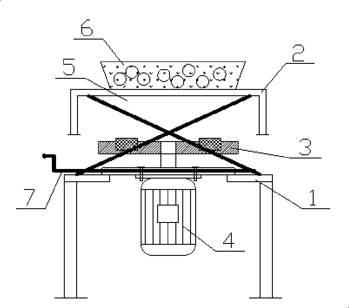
[0020] Embodiment: the structure of the present invention is as figure 1 , figure 2 As shown, the frame 1 and the supporting platform 2 are welded by profiles, a motor 4 with a rotating shaft facing upwards is installed in the middle of the frame 1, and a rotating tray 3 that can rotate along the center of the circle is placed on the upper end of the frame 1. The center of the rotating tray 3 is connected with the rotating shaft of the motor 4. The rotating tray 3 is made of iron plate. The rotating tray 3 is provided with a magnet installation slot 8 for installing a strong magnet 5. In the magnet installation slot 8, there are also slots for Disassemble the magnetic unloading hole 9 of the strong magnet 5, so that the strong magnet 5 can be directly fixed on the rotating tray 3 through the magnet installation slot 8, without fixing devices such as screws or pressure plates, reducing the magnetic loss of the strong magnet 5, and can improve Installation speed, the setting o...


PUM


Abstract

The invention discloses a magnetic grinder and a manufacturing method thereof which comprises the following steps: rotating magnetic lines are adopted to cause that grinding materials in a containing vessel move irregularly to implement the grinding operation to a workpiece; strong magnets arranged on a rotating tray are arranged asymmetrically to increase a magnetic action region of the magnetic grinder; a magnetic distance adjusting device for adjusting a distance between the rotating tray and the containing vessel is arranged on a support platform which is provided with the rotating tray and the containing vessel so as to ensure that the operation of the magnetic grinder is more convenient; the strong magnets arranged on the rotating tray of the magnetic grinder are arranged into two pairs, and magnetic poles of two adjusting strong magnets are opposite and arranged asymmetrically, thereby a nonmagnetic region in the middle of the magnetic grinder is reduced, the magnetic action region in the vessel is increased, the dead angle during the ground finish is decreased, and the efficiency and the processing effect of the magnetic grinder are further promoted. The magnetic distance adjusting device can reduce the action force between the strong magnets and a grinding pin, leads the vessel to be uplifted easily during the discharging and decreases the collision between the vessel and the support platform while placing the vessel.

Description

technical field [0001] The invention relates to a polishing device, in particular to a manufacturing method of a magnetic grinding machine and the magnetic grinding machine. Background technique [0002] The magnetic grinding machine puts the workpiece to be processed and the grinding needle into the container, and then sets a rotatable magnetic field at the lower end of the container. The rotating magnetic field drives the grinding needle in the container to move irregularly, and the moving grinding needle and the workpiece produce Intense collision and friction to achieve the effect of removing burrs and surface grinding of the workpiece. [0003] The magnets installed on the tray of the existing magnetic grinding machine are equidistant and symmetrically installed. In this way, in the production process, the magnetic field in the middle position of the symmetrical magnet is often weak, and the middle part is easy to accumulate material, forming dead angles, etc., reducing...

Claims


Application Information

Patent Timeline
Patent Type & Authority Applications(China)
IPC IPC(8): B24B31/112
Inventor 徐金发
Owner HUZHOU XING XING ABRASIVE
Why Eureka
Try Eureka