

Device for treating low concentration methane in ventilation air methane (VAM) of coal mine and method thereof
A low-concentration mine technology, applied in mining equipment, combustion methods, lighting and heating equipment, etc., can solve problems such as increased gas utilization, inability to deal with methane, and frequent changes in methane concentration in exhaust air, achieving small pressure loss and low operating costs Reduced effect
- Summary
- Abstract
- Description
- Claims
- Application Information
AI Technical Summary
Problems solved by technology
Method used
Image

Examples
Embodiment 1
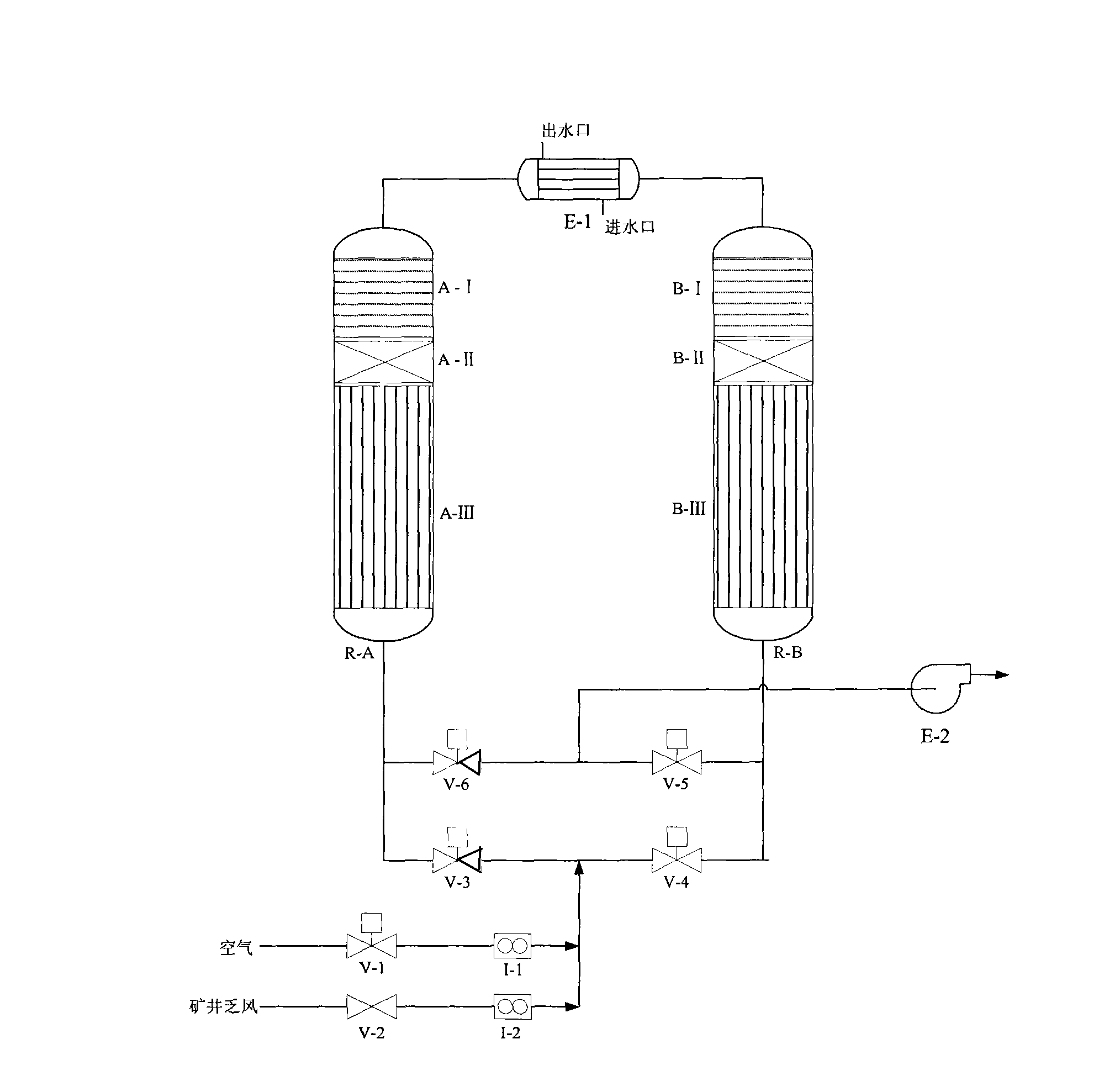
[0028] Applying the method described in the present invention to set up a set of processing capacity is 1000m 3 / h mine exhaust gas flow direction conversion catalytic combustion heating device, such as figure 1 shown. First, open the pneumatic three-way valve V-1 for air supply, close the gate valve V-2 at the mine gas inlet, heat exchanger E-1 does not take heat temporarily, and open the A heating equipment A-1 and B at the upper end of the catalytic reactor to heat The power supply of equipment B-1 starts heating; while heating, open the air inlet pneumatic three-way valve V-3, the air outlet pneumatic three-way valve V-5, close the air inlet pneumatic three-way valve V-4, the air outlet pneumatic three-way valve V -6, the air enters the catalytic reactor R-A from the air intake pneumatic three-way valve V-3 and is heated by the heating device A-1, and then enters the heating section B-1 at the top of the catalytic reactor R-B to continue heating, so that the hot air flow ...
Embodiment 2
[0031] The reaction device is as in Example 1, the catalyst and the regenerative fillers at both ends are preheated to the catalyst activation temperature of 450°C, and the exhaust gas flow rate of the mine is 1000m 3 / h, the methane concentration is 0.3%, the reversing period is 540s, the reaction can be carried out autothermally, and the methane conversion rate reaches over 95%.
experiment example 3
[0033] The reaction device is as in Example 1, the catalyst and the regenerative fillers at both ends are preheated to the catalyst activation temperature of 450°C, and the exhaust gas flow rate of the mine is 1000m 3 / h, the methane concentration is 0.6%, the reversing period is 540s, the methane conversion rate reaches over 95%, and the heat exchanger can remove part of the heat.
PUM
 Abstract
Description
Claims
Application Information