
Groove-tower combined two-stage heat-storage solar-heat power generation system

A technology of solar thermal power generation and solar energy, which is applied in the direction of solar thermal power generation, solar heating system, solar thermal energy, etc., can solve the problems of low heat collection temperature and difficulty in raising heat, so as to improve optical efficiency, improve thermal efficiency, and heat collection energy utilization reasonable effect

Inactive Publication Date: 2009-09-23
中金盛唐新能源科技(北京)有限公司
View PDF0 Cites 63 Cited by
  • Summary
  • Abstract
  • Description
  • Claims
  • Application Information

AI Technical Summary

Problems solved by technology

[0015] In view of this, the main purpose of the present invention is to provide a two-stage heat storage solar thermal power generation system combined with troughs and towers, to solve the problem of low heat collection temperature and difficulty in lifting of the trough solar thermal power generation system, and the single-tower solar thermal power generation system The optical efficiency of the heliostat field is greatly affected by the scale of the power plant, and it is difficult to increase the thermal efficiency of the system to reduce the investment in system equipment and the land area of ​​the power plant.

Method used


Image

  • Groove-tower combined two-stage heat-storage solar-heat power generation system
  • Groove-tower combined two-stage heat-storage solar-heat power generation system
  • Groove-tower combined two-stage heat-storage solar-heat power generation system

Examples


Embodiment Construction

[0044] In order to make the object, technical solution and advantages of the present invention clearer, the present invention will be described in further detail below in conjunction with specific embodiments and with reference to the accompanying drawings.

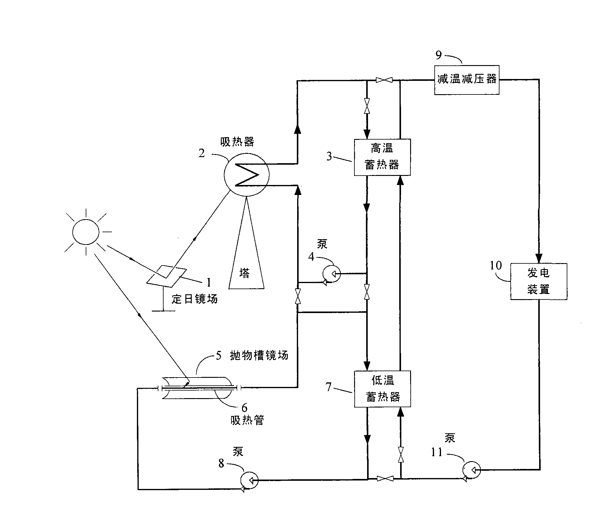
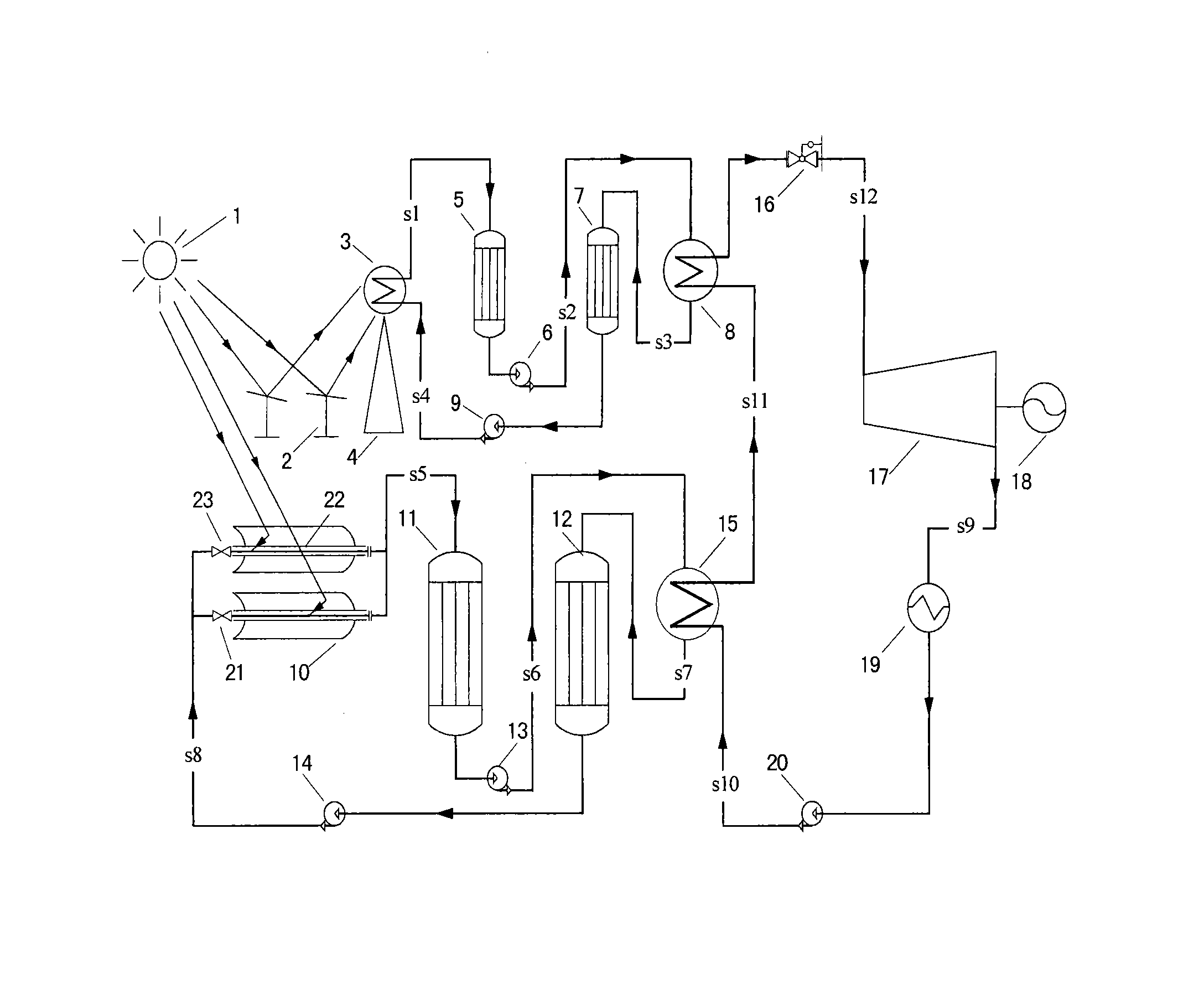
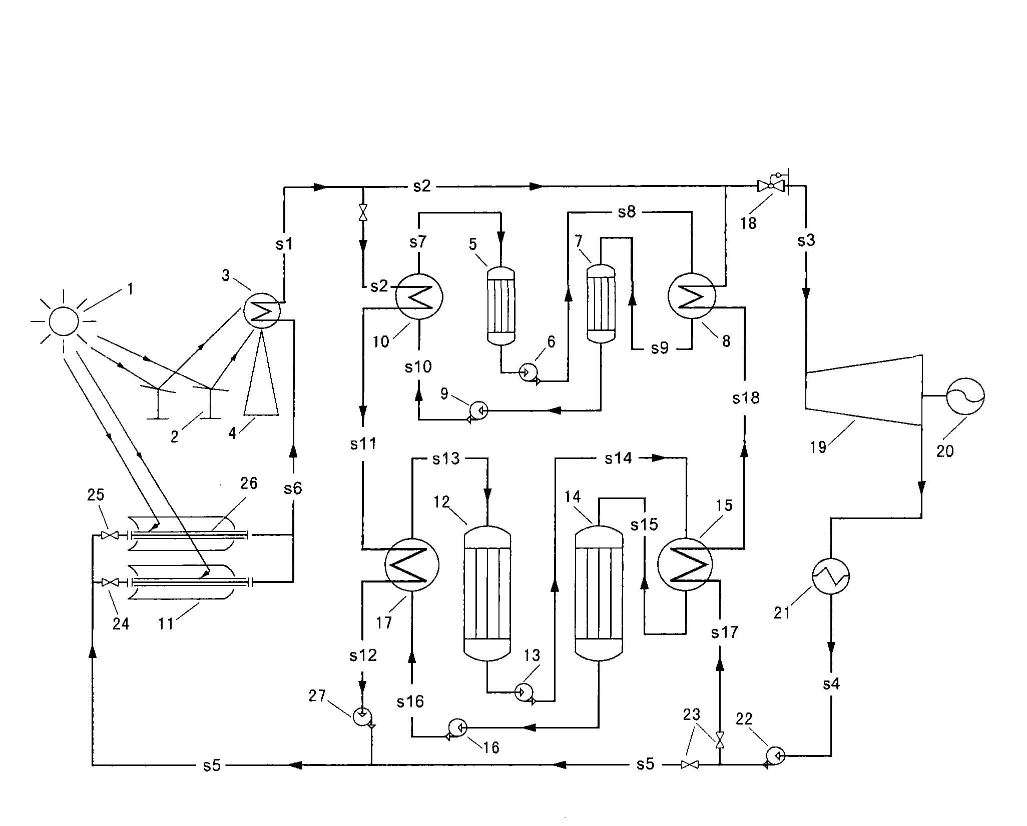
[0045] figure 1 Schematic diagram of the structure of the dual-stage heat storage solar thermal power generation system combined with trough towers provided by the present invention, the system at least includes a low-temperature trough-type heat collection and low-temperature heat storage subsystem, a high-temperature tower heat collection and high-temperature heat storage subsystem and a generator electronic system.

[0046] Among them, the low-temperature trough-type heat collection and heat storage subsystem is used to receive and gather solar radiation energy, convert the received solar radiation energy into medium-temperature heat energy, and send it to the high-temperature tower heat collection and high-temperature...


PUM


Abstract

The invention discloses a groove-tower combined solar-heat power generation system, which comprises a subsystem for low-temperature groove-type heat collection and low-temperature heat storage, a subsystem for high-temperature tower-type heat collection and high-temperature heat storage, as well as a power generation subsystem, wherein the subsystem for low-temperature groove-type heat collection and low-temperature heat storage is used for receiving and gathering solar radiation energy, converting the received solar radiation energy into medium-temperature heat energy and conveying the medium-temperature heat energy to the subsystem for high-temperature tower-type heat collection and high-temperature heat storage or a low-temperature heat accumulator; the subsystem for high-temperature tower-type heat collection and high-temperature heat storage is used for receiving and gathering solar radiation energy, converting the received solar radiation energy into high-temperature heat energy and conveying the high-temperature heat energy to a power subsystem or a high-temperature heat accumulator; and the power subsystem is used for converting the received heat energy into electric energy and outputting the electric energy. The system solves the problems that a groove-type solar-heat power generation system is low in heat-collecting temperature and difficult to promote; the optical efficiency of a heliostat filed of a simple-tower solar-heat power generation system is greatly affected by the scale of power plants; and the simple-tower solar-heat power generation system is not easy to maximize. The system has the advantages of reducing initial cost and occupied area.

Description

technical field [0001] The invention relates to the technical field of renewable energy applications, in particular to a dual-stage heat storage solar thermal power generation system combined with tanks and towers. Background technique [0002] The invention is a new system integration mode in solar thermal power generation technology. At present, the system types and system characteristics of existing solar thermal power generation technologies are summarized as follows: [0003] 1. Parabolic trough solar thermal power generation system [0004] The parabolic trough solar thermal power generation system is a form of solar thermal power generation that uses a trough-type line-focusing parabolic reflector to meet the concentration requirements. The trough-type parabolic reflector performs one-dimensional tracking of the sun, and its concentration ratio is between 40 and 80. The heat collection temperature is generally lower than 400°C. At present, most parabolic trough sol...

Claims


Application Information

Patent Timeline
IPC IPC(8): F03G6/06F24S23/71F24S20/20
CPCY02E10/42Y02E10/46Y02E10/41Y02P80/15
Inventor 金红光韩巍林汝谋宿建峰
Owner 中金盛唐新能源科技(北京)有限公司
Learn More