Method and device for measuring shape and size of workpiece with high-temperature end and low-temperature end on line

A measuring device and low-temperature end technology, which is used in the on-line measurement of the shape and size of the deformation zone in dieless drawing, and the on-line measurement of the shape and size of workpieces coexisting at the high-temperature end and the low-temperature end. Problems such as online measurement of workpiece shape and size coexist in low temperature area, no high temperature end and low temperature end, to achieve the effect of fast measurement speed, improved efficiency and high measurement accuracy

Inactive Publication Date: 2009-09-23
UNIV OF SCI & TECH BEIJING
View PDF1 Cites 17 Cited by
  • Summary
  • Abstract
  • Description
  • Claims
  • Application Information

AI Technical Summary

Problems solved by technology

The coexistence of high temperature end and low temperature end of the workpiece in the deformation zone brings many difficulties to image measurement: parameter settings such as aperture size and exposure time cannot be suitable for high temperature area and low temperature area at the same time
At present, there is no report on the online measurement of the shape and size of workpieces with high temperature and low temperature using image processing methods

Method used


Image

  • Method and device for measuring shape and size of workpiece with high-temperature end and low-temperature end on line
  • Method and device for measuring shape and size of workpiece with high-temperature end and low-temperature end on line
  • Method and device for measuring shape and size of workpiece with high-temperature end and low-temperature end on line

Examples


Embodiment Construction

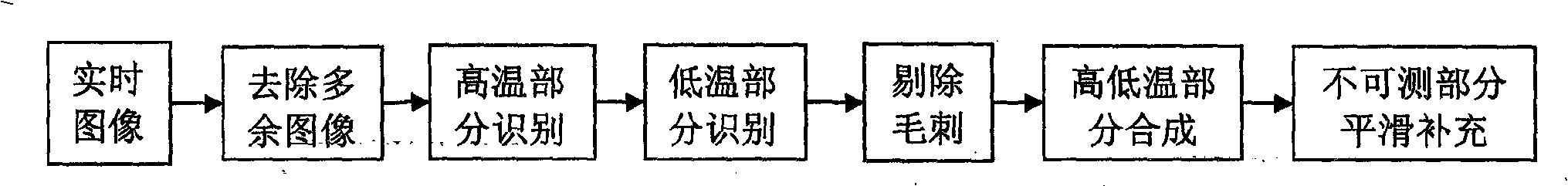
[0025] An example of the specific implementation of the present invention will be described below in conjunction with the accompanying drawings.

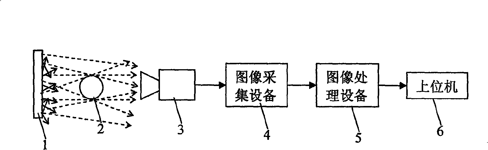
[0026] Diffuse backlight 1 adopts a backlight composed of compactly arranged high-brightness LED substrates and frosted glass, area array CCD camera 3 is Panasonic CAMERAANPVC1210, image acquisition device 4 is Panasonic PV500 image acquisition equipment, and image processing equipment 5 is Panasonic PV500 image processing Device, the upper computer 6 is NI PXI-1030 produced by National Instruments, and LabVIEW 8.5 software is installed in the upper computer to realize data acquisition and processing.

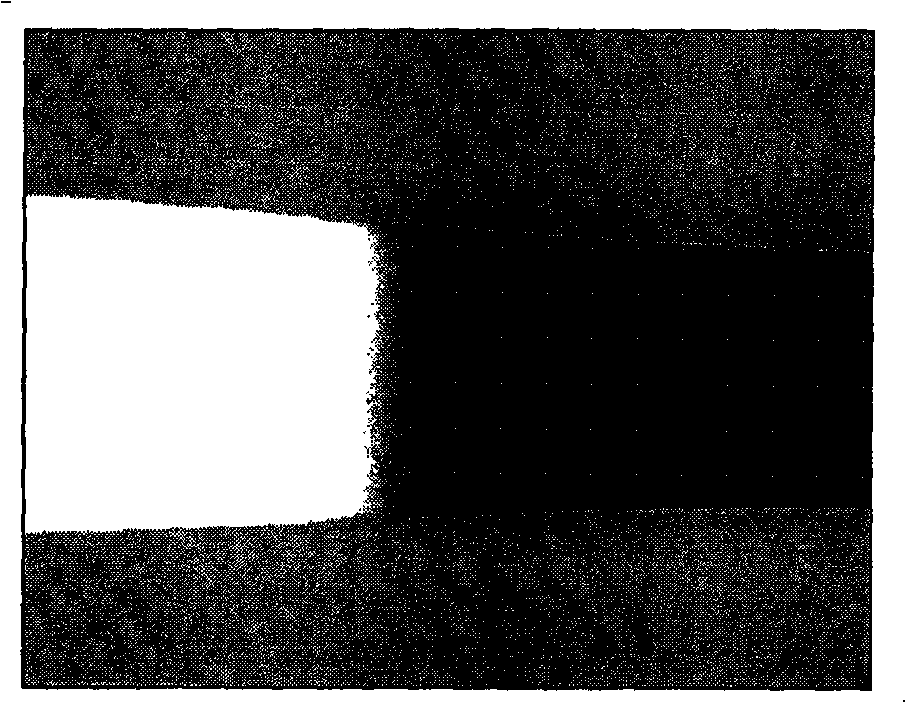
[0027] The workpiece 2 to be tested is installed in the dieless drawing equipment, and undergoes dieless drawing deformation. The diffuse backlight 1 and the area array CCD camera 3 are respectively placed on both sides of the workpiece 2, and the optical axis of the area array CCD camera 3 is perpendicular to the axial direction of ...


PUM


Abstract

The invention belongs to the technical field of on-line detection of shape and size of workpieces, and particularly relates to a method and a device for measuring shape and size of a workpiece with a high-temperature end and a low-temperature end on line. The device consists of a diffusion backlight, a plane array CCD camera, an image acquisition device, an image processing device and a host computer; a detected workpiece is positioned between the diffusion backlight and the plane array CCD camera, and an optical axis of the plane array CCD camera is vertical to the diffusion backlight; under the irradiation of the diffusion backlight, a low-temperature part of the workpiece forms a dark space to generate contrast so as to form an image edge capable of being detected; the brightness of a high-temperature part of the workpiece is higher than the background of the diffusion backlight to generate contrast so as to form an image edge capable of being detected; and the plane array CCD camera transmits acquired workpiece images to the image acquisition device in real time, the image processing device finishes processing the images, and finally the diameter value of each axial position in a deformation zone is transmitted to the host computer. The method and the device can finish precise on-line measurement of the shape and the size of the workpiece with the high-temperature end and the low-temperature end, the measurement precision is high, the measurement speed is high, the measurement device is simple, and the hardware components are easily bought.

Description

technical field [0001] The invention belongs to the technical field of on-line detection of the shape and size of workpieces, in particular to an online measurement method and device for the shape and size of workpieces with both high-temperature and low-temperature ends, and is especially suitable for on-line measurement of the shape and size of deformation zones in dieless drawing. Background technique [0002] In the process of metal thermal processing or heat treatment, the temperature field distribution is often uneven, and there is often a phenomenon of coexistence of high temperature and low temperature ends, such as the distribution of temperature field in the deformation zone in the process of dieless drawing. Dieless drawing is a method of metal forming without using a mold. By applying a certain tension to both ends of the workpiece and heating and cooling the local part of the wire at the same time, the deformation caused by the tension is concentrated in the part...

Claims


Application Information

Patent Timeline
Patent Type & Authority Applications(China)
IPC IPC(8): G01B11/24G01B11/08B21C51/00
Inventor 谢建新何勇刘雪峰陈松
Owner UNIV OF SCI & TECH BEIJING
Why Eureka
Try Eureka