Engine life predication apparatus and refrigerator

A technology of life prediction and engine, which is applied in the direction of engine testing, household refrigeration devices, measuring devices, etc., can solve the problems of increased manufacturing cost and low reliability, and achieve the effects of improving accuracy, accurate life, and easy detection.

Inactive Publication Date: 2009-09-23
DAIKIN IND LTD
View PDF4 Cites 9 Cited by
  • Summary
  • Abstract
  • Description
  • Claims
  • Application Information

AI Technical Summary

Problems solved by technology

[0007] However, the technologies described in Patent Documents 1 to 4 have problems of low reliability and increased manufacturing cost because sensors such as an engine rotation speed detector and a torque detector are required.

Method used


Image

  • Engine life predication apparatus and refrigerator
  • Engine life predication apparatus and refrigerator
  • Engine life predication apparatus and refrigerator

Examples


no. 1 Embodiment approach

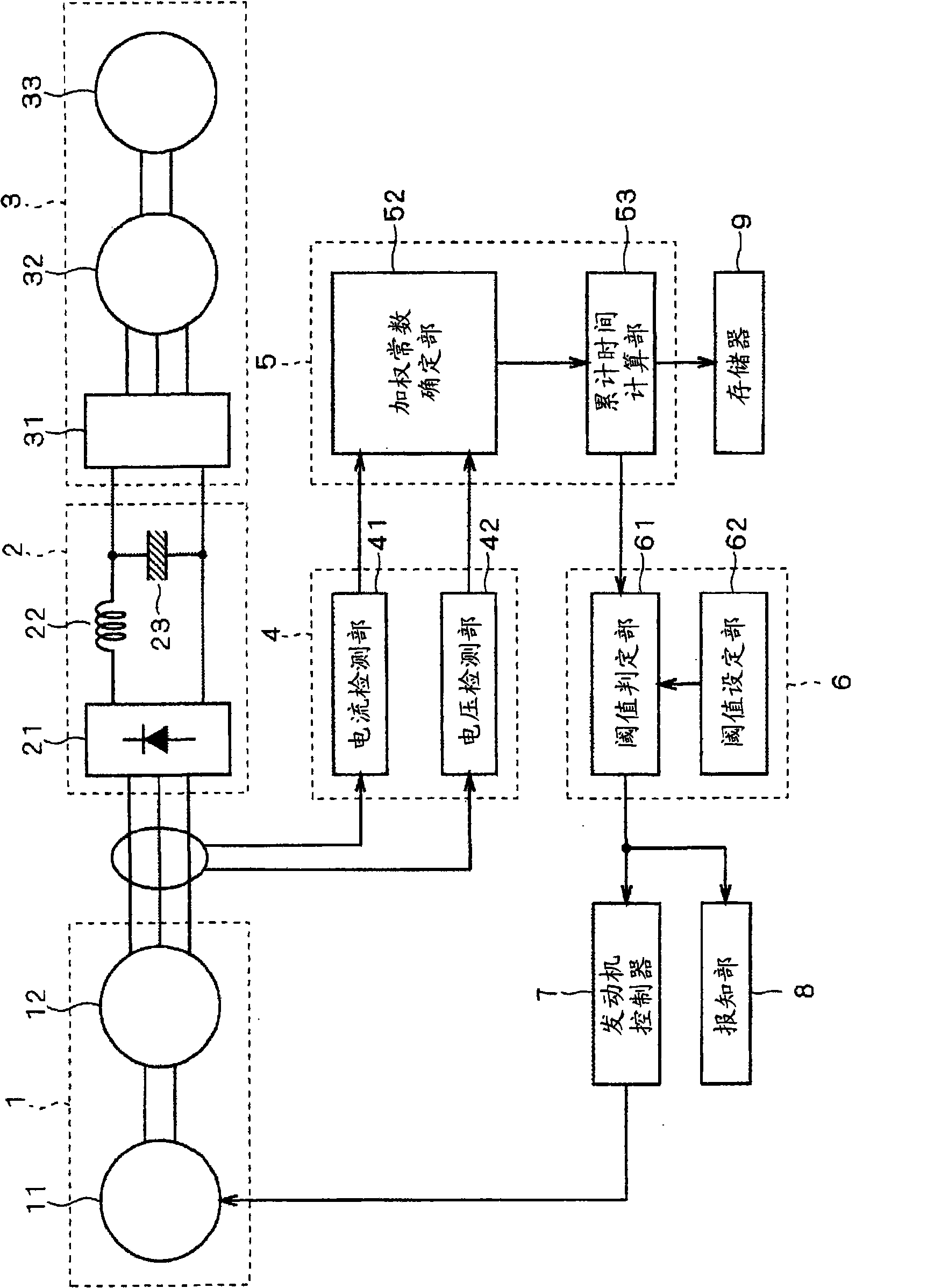
[0050] figure 1 A schematic configuration diagram showing a refrigeration device to which the engine life prediction device according to the first embodiment of the present invention is applied.

[0051] The refrigerating device includes: an engine generator 1 , an inverter 2 , a compressor drive unit 3 , a detection unit 4 , a calculation unit 5 , a determination unit 6 , an engine controller 7 , a notification unit 8 and a nonvolatile memory 9 . This refrigerating device is mounted on a trailer, for example, and has a mechanism (heat exchanger, fan, etc.) for cooling the interior of the trailer. However, illustration is omitted because it is not the essence of the present invention.

[0052] The engine generator 1 has an engine 11 and a generator 12 . The generator 12 is driven by the engine 11 as a power source, for example, generates three-phase alternating current, and supplies it to the converter 2 . In addition, the generator 12 may be a generator that generates singl...

no. 2 Embodiment approach

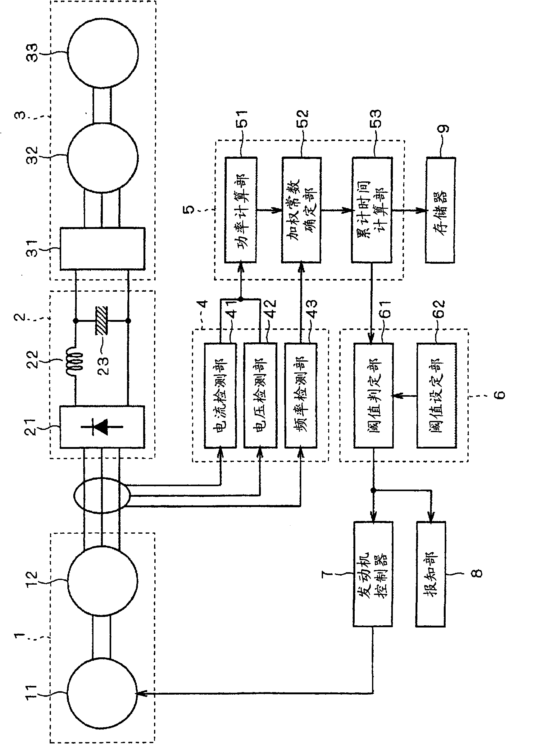
[0079] image 3 A schematic configuration diagram showing a refrigeration device to which an engine life prediction device according to a second embodiment of the present invention is applied. Compared with the first embodiment, the detection unit 4 further includes a frequency detection unit 43 , and the calculation unit 5 further includes a power calculation unit 51 .

[0080] The frequency detection unit 43 detects the frequency of the AC voltage output from the engine generator 1 .

[0081] The power calculation unit 51 calculates power using the current value detected by the current detection unit 41 and the voltage value detected by the voltage detection unit 42 .

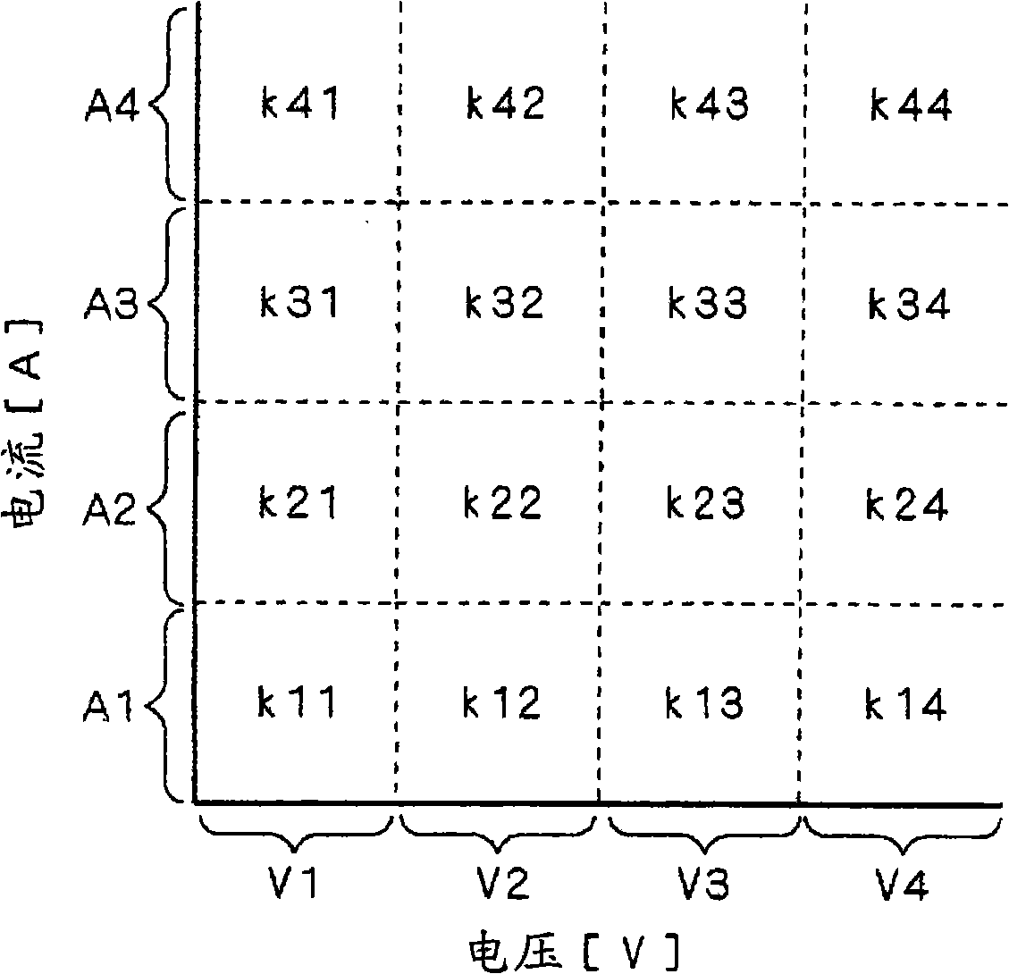
[0082] The weight constant determination unit 52 calculates the rotation speed of the engine 11 based on the frequency detected by the frequency detection unit 43 , and determines the weight constant based on the power and the rotation speed calculated by the power calculation unit 51 . Specifically, Figu...

no. 3 Embodiment approach

[0090] Figure 5 A schematic configuration diagram showing a refrigeration device to which an engine life prediction device according to a third embodiment of the present invention is applied. Compared with the second embodiment, the detection unit 4 detects the direct current output from the converter 2 .

[0091] The current detection unit 41 detects the current value output from the converter 2 on the low potential side. The voltage detection unit 42 detects a voltage between a high potential and a low potential output from the converter 2 .

[0092] The frequency detection unit 43 detects the frequency of the AC voltage from the engine generator 1 by detecting the pulsation frequency of the DC voltage output from the converter 2 . When the generator 12 is a three-phase rotating electric machine, generally, there is a relationship that the pulsation frequency of the DC voltage from the converter 2 is six times the frequency of the AC voltage from the engine generator 1 . ...


PUM


Abstract

An engine life prediction apparatus produced at a low cost and having a high reliability is provided. A current detecting section (41) and a voltage detecting section (42) detect the value of a current and the value of a voltage which are outputted by an engine generator (1), respectively. An arithmetic section (5) determines a weight constant from the current value and the voltage value, assigns the weight to the operating time of an engine (11) by using the weight constant, and integrates the weighted operating time to calculate the integrated time. A judgment section (6) compares the integrated time with a reference time and, when judging that the integrated time exceeds the reference time, notifies it to a report section (8). The report section (8) having received the notification reports it to the outside. The current detecting section (41) and the voltage detecting section (42) can be configured by an electrical circuit. Thus, the engine life can be predicted at the low cost and with the high reliability.

Description

technical field [0001] The invention relates to an engine life prediction device and a refrigeration device, in particular to life prediction using an engine as a power source for a generator. Background technique [0002] Patent Documents 1 to 4 disclose techniques for predicting the life of an engine using the rotational speed, output torque, power consumption, and the like of the engine. For example, in Patent Document 1, an engine speed sensor and a rack position sensor are used to detect the engine speed and rack position (a proxy value for engine torque), and weights are determined based on the detected speed and rack position. Weights to weight the engine run time and calculate the life of the engine. [0003] Patent Document 1: Japanese Patent Application Laid-Open No. 11-211622 [0004] Patent Document 2: Japanese Patent Application Laid-Open No. 06-010748 [0005] Patent Document 3: Japanese Patent Laid-Open No. 2001-011900 [0006] Patent Document 4: Japanese ...

Claims


Application Information

Patent Timeline
Patent Type & Authority Applications(China)
IPC IPC(8): G01M15/02G01R31/34H02K15/00G01M99/00
CPCY02B30/741Y02B40/32G07C3/00F25D11/003F25B2700/151F25B2600/021F25B49/005F25D29/008Y02B30/70Y02B40/00
Inventor 松野澄和仲田哲雄
Owner DAIKIN IND LTD
Why Eureka
Try Eureka