Ultra thin type LCD use backlight module taking LED as light source

A technology of LED light source and backlight module, which is applied in the direction of semiconductor devices, light sources, point light sources, etc. , to achieve the effect of improving reflection efficiency and improving light source utilization

Inactive Publication Date: 2009-09-30
SHENZHEN DIQUANG ELECTRONICS CO LTD
View PDF3 Cites 54 Cited by
  • Summary
  • Abstract
  • Description
  • Claims
  • Application Information

AI Technical Summary

Problems solved by technology

As far as the existing LED production technology is concerned, although white LED chips can be directly produced, their cost is high and their luminous efficiency is low, so they are rarely used commercially.
The white light generation method generally used in the industry is to encapsulate the red, green, and blue LED chips into a light-emitting element with epoxy resin, and adjust the current of the three LED chips to generate white light. Best, in order to improve the light mixing effect, it is necessary to add a light mixing element between the light guide plate and the LED package component or increase the size of the light guide plate and the distance between the display area and the LED package component, and these means and reduce the size of the backlight module purpose is contradictory
[0008] The inherent defects of the existing technology make it impossible to overcome the bottleneck in the thinning process of large-scale liquid crystal displays using direct-lit backlights. Even if improvements are made, the problem cannot be fundamentally solved. limited and cannot be applied to large ultra-thin display devices

Method used


Image

  • Ultra thin type LCD use backlight module taking LED as light source
  • Ultra thin type LCD use backlight module taking LED as light source
  • Ultra thin type LCD use backlight module taking LED as light source

Examples


Embodiment Construction

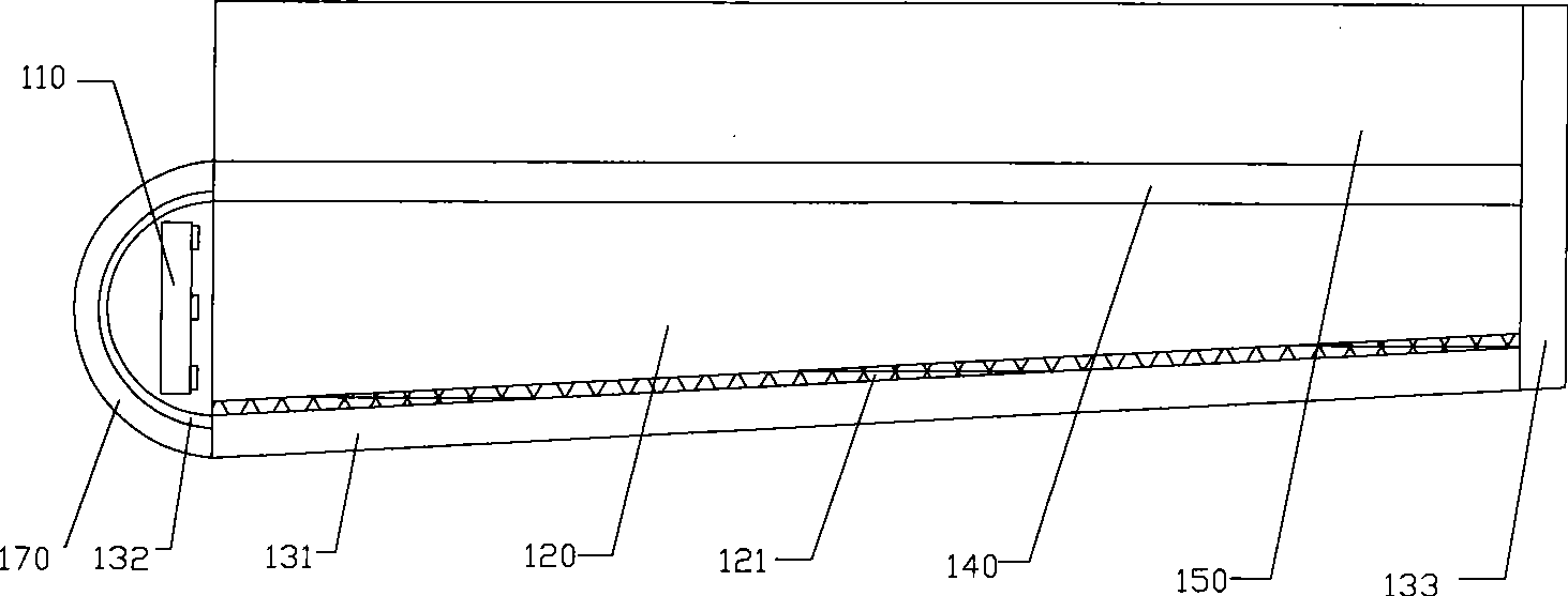
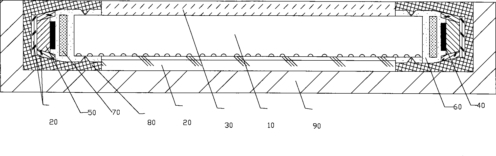
[0032] The present invention will be described in detail below in conjunction with the accompanying drawings. The edge-lit backlight module of the present invention has two realization forms of double-side light source and single-side light source.

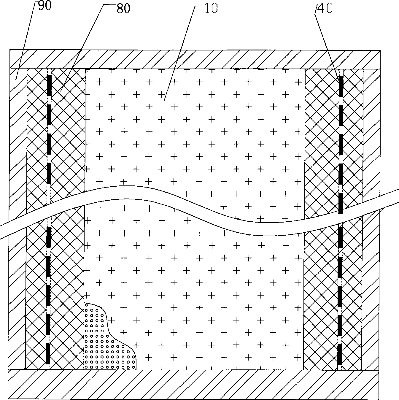
[0033] In order to achieve a better brightness effect, an embodiment of the present invention is to use double-sided light sources. figure 2 It is a schematic cross-sectional top view of the double-side light source side-light LED backlight module of the present invention, image 3 It is a front view cross-sectional schematic diagram of the double-side light source side-light LED backlight module of the present invention, Figure 4 yes figure 2 The enlarged schematic diagram of the partial section. It can be seen from the figure that the LED backlight module includes a light source and a light guide plate, and the light sources on both sides are arranged symmetrically. The bracket bars 80 are respectively connected to both s...


PUM

PropertyMeasurementUnit
thicknessaaaaaaaaaa
thicknessaaaaaaaaaa

Abstract

The invention relates to a side light type LED backlight module. The backlight module comprises a light guiding plate made of a transparent material, an LED light source, a fluorescent film, and a transparent heat conducting material. At least one side of the light guiding plate is connected with support bars; and an accommodating space is formed between the light guiding plate and the support bars. The LED light source comprises a circuit board and a plurality of LED chips connected with the circuit board. The fluorescent film is arranged between the LED chips and the light guiding plate, and mixes the light rays emitted by the LED chips so as to produce white backlight or other required color backlights; and the LED light source and the fluorescent film are positioned inside the accommodating space. The transparent heat conducting material is filled in the accommodating space between the light guiding plate and the support bars. The LED backlight module integrally encapsulates a plurality of LED chips, thereby solving the problems of low light source density and insufficient brightness caused by the separately encapsulated LED chips in array. Consequently, the side light type backlight module is applied to large-scale ultra thin type LCD devices.

Description

technical field [0001] The invention relates to a backlight module of a liquid crystal display, in particular to a side-light backlight module for a large ultra-thin liquid crystal display using LEDs as a light source. Background technique [0002] Since the liquid crystal display itself does not emit light, a backlight module is required to provide a light source for the liquid crystal display. As one of the key components of liquid crystal display, the backlight module has been widely used in computer display screens, liquid crystal televisions, etc. at present. The backlight module is placed under the liquid crystal display to provide a certain brightness and high uniformity of light to the display, by controlling the pixel electrodes on the display to form different brightness, different chromaticity and different grayscale and color pictures. [0003] The backlight module is generally composed of a light source and a light guide plate. The light source generally uses a...

Claims


Application Information

Patent Timeline
Patent Type & Authority Applications(China)
IPC IPC(8): G02F1/13357G02B1/04G02B1/10G02B6/00F21V29/00F21V23/06F21Y101/02F21Y105/10F21Y115/10
Inventor 宋义苏遵惠
Owner SHENZHEN DIQUANG ELECTRONICS CO LTD
Why Eureka
Try Eureka