Air conditioning system for vehicle

An air-conditioning system and vehicle technology, which is applied to vehicle parts, air handling equipment, lighting and heating equipment, etc., can solve problems such as inability to cool down, and achieve the effects of simplified structure, high heat transfer efficiency, and simple structure

Inactive Publication Date: 2009-09-30
CALSONIC KANSEI CORP
View PDF1 Cites 34 Cited by
  • Summary
  • Abstract
  • Description
  • Claims
  • Application Information

AI Technical Summary

Problems solved by technology

However, the system cannot cool

Method used


Image

  • Air conditioning system for vehicle
  • Air conditioning system for vehicle
  • Air conditioning system for vehicle

Examples


no. 1 Embodiment approach

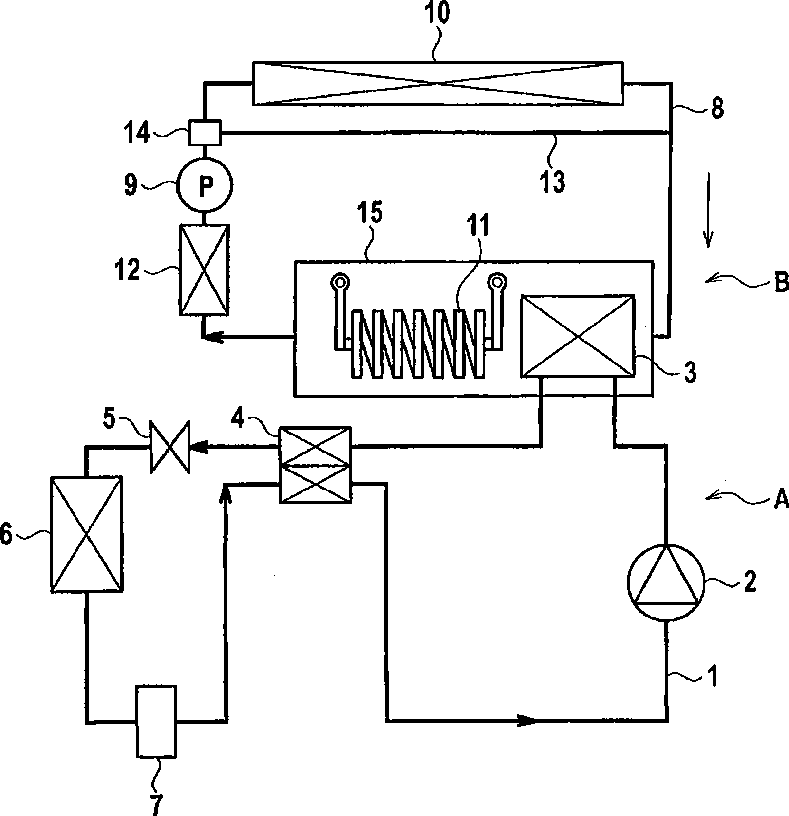
[0045] figure 1 It is a system configuration diagram of the vehicle air conditioning system according to the first embodiment of the present invention. The vehicle air conditioning system according to the present embodiment is an air conditioning system in which a heat pump air conditioner A and a heating circulation device B are combined.

[0046] The heat pump air conditioner A has a first circulation path 1 in which carbon dioxide is sealed as a first refrigerant, and the first circulation path 1 includes a compressor 2, a water-cooled condenser 3 as a condenser, and an internal heat exchanger in this order. 4. Expansion valve 5, evaporator 6 and gas-liquid separator 7 as expansion components.

[0047] The compressor 2 compresses the sucked relatively low-temperature and low-pressure first refrigerant and discharges it as a high-temperature and high-pressure refrigerant.

[0048] The water-cooled condenser 3 is arranged in the equipment storage chamber 15 in the second ci...

no. 2 Embodiment approach

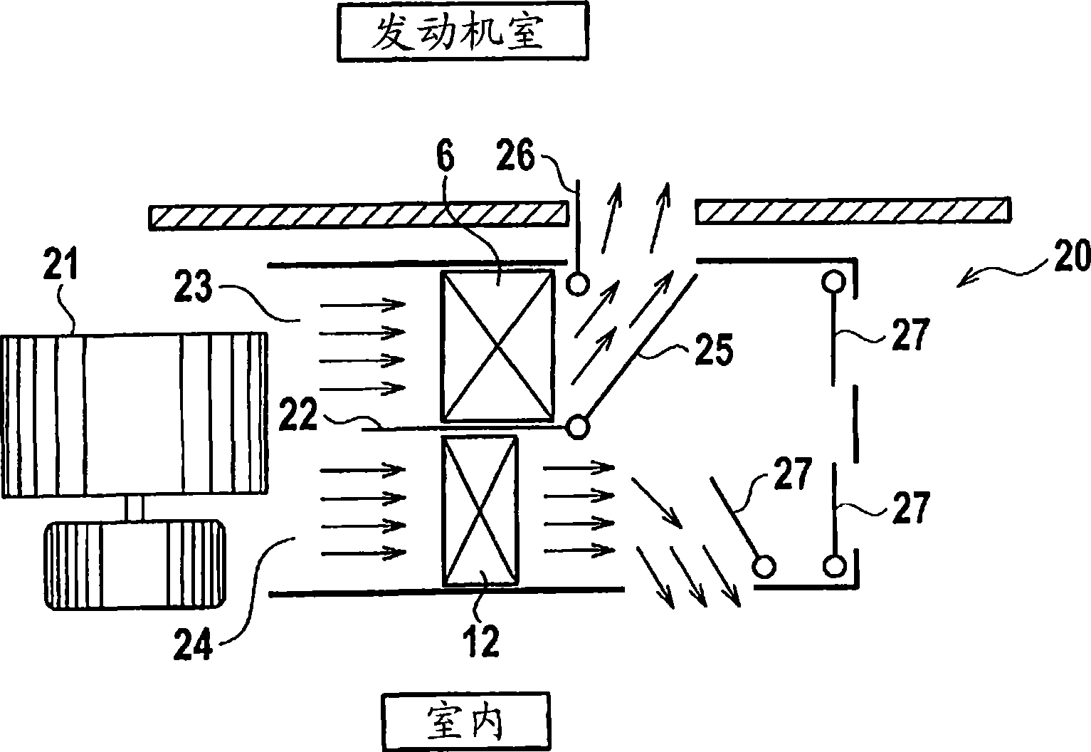
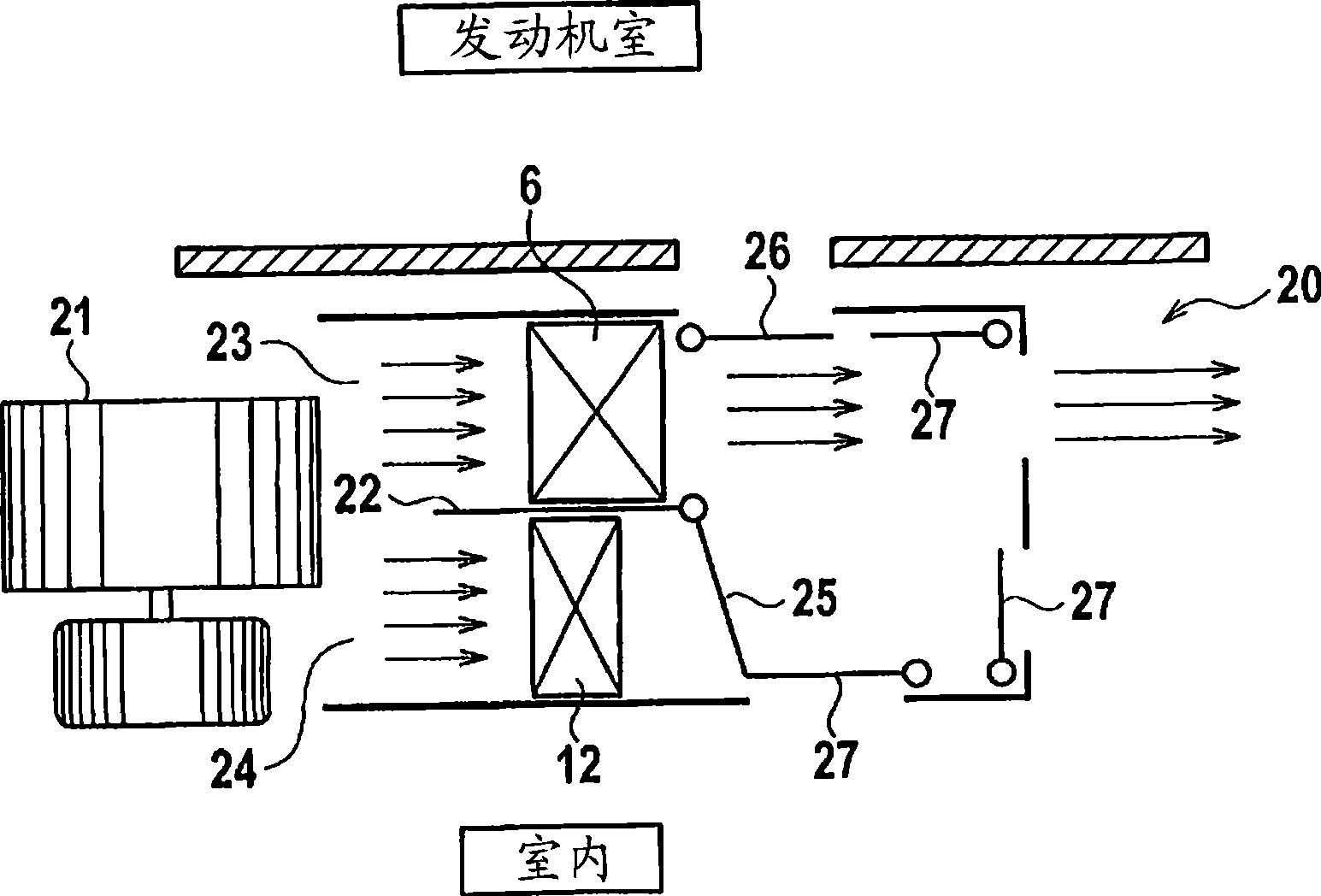
[0082] The configuration of the heat pump air conditioner A and the heating circulation device B in the vehicle air conditioning system of the second embodiment is the same as that of the first embodiment, and the configuration of the air conditioning duct 20 is different. Figure 4 , Figure 5 is a schematic structural diagram showing the structure of the air-conditioning duct 20, Figure 4 Indicates the structure during heating, Figure 5 Indicates the structure during cooling.

[0083] In the air-conditioning duct 20 of the second embodiment, two blowing fans 30, 31 are arranged side by side. One blowing fan 30 is provided on the flow path 23 on the side of the evaporator 6 for easy air blowing, and the other blowing fan 31 is easy for blowing air. The means of blowing air is provided in the flow path 24 on the side of the heater core 12 . An air distribution door 32 is provided at the upstream end of the partition 22 , and the air distribution ratio of the air volume fr...

no. 3 Embodiment approach

[0091] Figure 6 It is a system configuration diagram of the vehicle air conditioning system of the third embodiment. Such as Figure 6 As shown, the third embodiment is compared with the first embodiment in that in the third embodiment, a flow path switching valve 42 is provided between the expansion valve 5 and the evaporator 6 . The first refrigerant can be returned to the evaporator 6 via the motor 40 and the inverter 41 by the flow path switching valve 42 .

[0092] Since the other configurations are the same as those of the first embodiment, the same components are assigned the same reference numerals and their descriptions are omitted.

[0093] During heating, the flow path can be switched by the flow path switching valve 42 so that the second refrigerant that has passed through the expansion valve 5 is sent to the evaporator 6 via the motor 40 and the inverter 41 . This also enables the first refrigerant to be heated by the heat generated in the electric motor 40 an...


PUM


Abstract

An air conditioning system for a vehicle includes a heat pump type cooling device (A) having a first circulation route (1), and also includes a circulation device (B) for heating having a second circulation route (8). A water-cooled condenser (3) in the first circulation route (1) is placed in the second circulation route (8) and releases heat of a first refrigerant to a second refrigerant. A flow path change valve (14) for changing between the radiator (10) side and a radiator bypass flow path (13) is provided in the second circulation route (8). In heating operation, the second refrigerant is caused to flow to the radiator bypass flow path (13) by the flow path change valve (14) and air heated by a heater core (12) is introduced as air conditioned air into a vehicle interior. In cooling operation, the second refrigerant is caused to flow to the radiator by the flow path change valve (14) and air cooled by an evaporator (6) is introduced as air conditioned air into the vehicle interior.

Description

technical field [0001] The present invention relates to a vehicle air conditioning system capable of heating and cooling. Background technique [0002] As a related vehicle air-conditioning system, there is Japanese Patent Laid-Open No. 2002-98430 ( figure 1 , FIG. 9, the fourth embodiment, etc.) disclosed vehicle air conditioning system. The vehicle air conditioning system includes a heat-pump type air conditioner having a first circulation flow path for a first refrigerant cycle and a heating cycle device having a second circulation flow path for a second refrigerant cycle. . [0003] A compressor, a radiator of the internal heat exchange unit, an indoor heat exchanger, an expansion valve, and an outdoor heat exchanger are provided in the first circulation flow path of the heat pump air conditioner. The indoor heat exchanger is arranged in the air-conditioning duct opening to the vehicle cabin. The first circulation flow path has many switching valves for switching bet...

Claims


Application Information

Patent Timeline
Patent Type & Authority Applications(China)
IPC IPC(8): B60H1/22
CPCF25B40/00B60H2001/00957F25B9/008F25B2339/047F25B2309/061B60H2001/00928B60H1/00921B60H1/00899B60H2001/00121B60H2001/00178B60H1/32281
Inventor 高桥寅秀吉冈宏起藤田隆司
Owner CALSONIC KANSEI CORP
Why Eureka
Try Eureka