Fuel injector having a solenoid valve with a spherical seat

A fuel injector and fuel injection technology, which is applied in the direction of fuel injection devices, special fuel injection devices, charging systems, etc., can solve the problems of electromagnetic valve wear and electromagnetic valve influence, etc., to reduce bouncing and improve damping characteristics , The effect of valve coordination improvement

Inactive Publication Date: 2009-09-30
ROBERT BOSCH GMBH
View PDF1 Cites 11 Cited by
  • Summary
  • Abstract
  • Description
  • Claims
  • Application Information

AI Technical Summary

Problems solved by technology

This leads to wear in terms of the operating time of the solenoid valve, which has a not insignificant effect on the function of the solenoid valve thus constructed

Method used


Image

  • Fuel injector having a solenoid valve with a spherical seat

Examples


Embodiment Construction

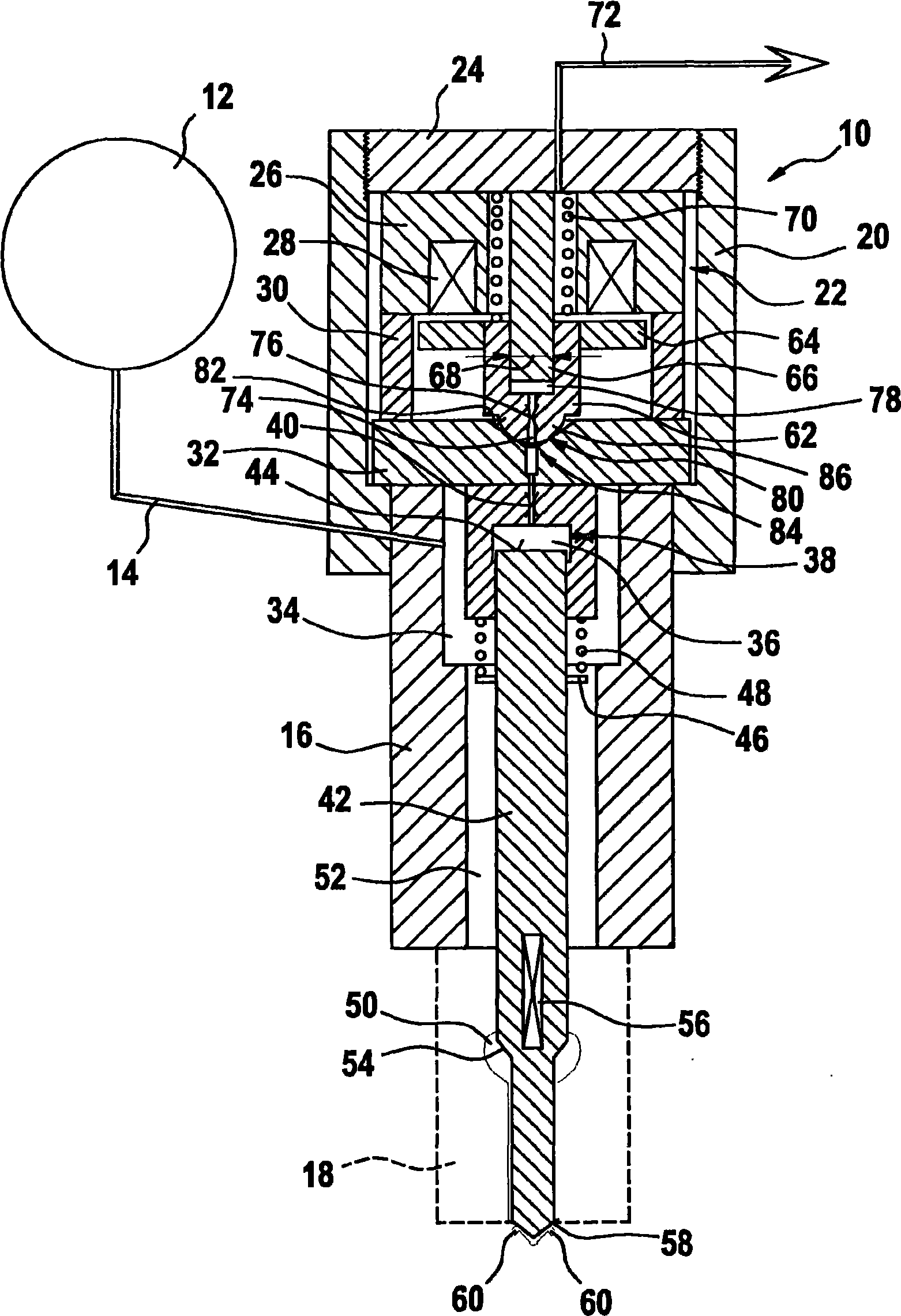
[0013] It can be seen from the figure that the fuel injector 12 passes through a system pressure p sys The pressure accumulator 12 is charged with fuel under high pressure. System pressure p in pressure accumulator 12 sys It is generated by a high-pressure delivery device (not shown in the figure), such as a high-pressure pump, and passes from the pressure accumulator 12 via the high-pressure line 14 to the fuel injector 10 . The high-pressure line 14 leads into the injector housing 16 and applies the pressure chamber indicated by reference numeral 34 at the system pressure p sys under system pressure.

[0014] According to the figure, the fuel injector 10 comprises, in addition to the injector housing 16, a nozzle body 18 which is only dotted here and an actuator housing 20, in which an actuator configured as a solenoid valve 22 is mounted. mechanism. The actuator housing 20 is closed by a housing cover 24 . In this figure the housing cover 24 is provided with an externa...


PUM


Abstract

The invention relates to a fuel injector (10) for injecting fuel into a combustion chamber of an internal combustion engine. An injection valve element (42) is actuated via pressure relief of a control space (36). Said control space (36) is loaded by a system pressure Rhosys. The control space (36) is relieved of pressure via a solenoid valve (22) of pressure-equalized configuration, the valve element (62) of which opens or closes a valve seat (80). The valve seat (80) comprises a spherical surface (86).

Description

Background technique [0001] An injector for injecting fuel into a combustion chamber of an internal combustion engine is known from EP-A 1 612 403, wherein the injection valve element is controlled by an electromagnetically driven control valve. The discharge throttle from the control chamber to the fuel return can be closed or released by means of the control valve. The control chamber is delimited on one side by a control piston, by means of which an injection valve element is controlled which discharges into at least one injection opening in a combustion chamber of the internal combustion engine. The discharge throttle is accommodated in a component which is provided with a narrowed valve seat on the side facing away from the control chamber. A closure element is displaceable in the valve seat, which closure element is connected to the armature of the solenoid valve. For this purpose, an edge is formed on the closing element, which edge is displaceable relative to the con...

Claims


Application Information

Patent Timeline
Patent Type & Authority Applications(China)
IPC IPC(8): F02M45/02F02M47/02F02M63/02F02M63/00
CPCF02M63/0015F02M2200/28F02M47/027F02M45/02F02M63/0225F02M63/0071F02M63/008F02M63/007
Inventor N·艾森门格尔H-C·马盖尔H-C·马盖尔
Owner ROBERT BOSCH GMBH
Why Eureka
Try Eureka