


Quick Research
Generate reliable direction feasibility study reports for your R&D in just a few steps.

Technical Q&A
Discover and master advanced knowledge NOW. Basics, ideas, possibilities, all at once.

Find Solutions
As an expert in R&D theories, this can generate solutions to your technical problems instantly.

Evaluate Feasibility
Analyze your overall solution with one click, know your potential R&D risks in advance.

Monitor Landscape
Get weekly tech updates, stay abreast of the latest tech innovations and key insights.
Ultrasonic high-gradient magnetic separation device
A magnetic separation device and ultrasonic technology, applied in the field of mining machinery, can solve the problems of low frequency of mechanical vibration, long distance between vibration source and magnetic medium, and less obvious effect, so as to improve the grade of concentrate, reduce gangue inclusion, prevent blocking effect
- Summary
- Abstract
- Description
- Claims
- Application Information
AI Technical Summary
Problems solved by technology
Method used
Image

Examples
Embodiment 1
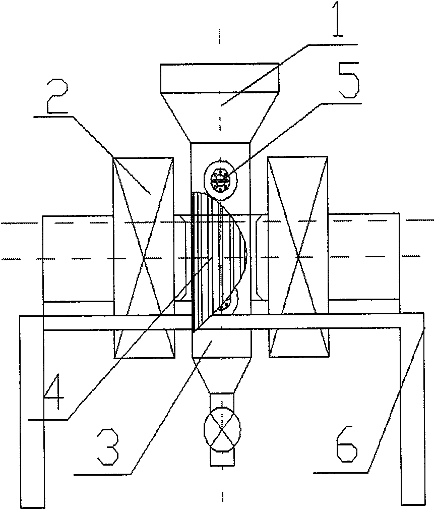
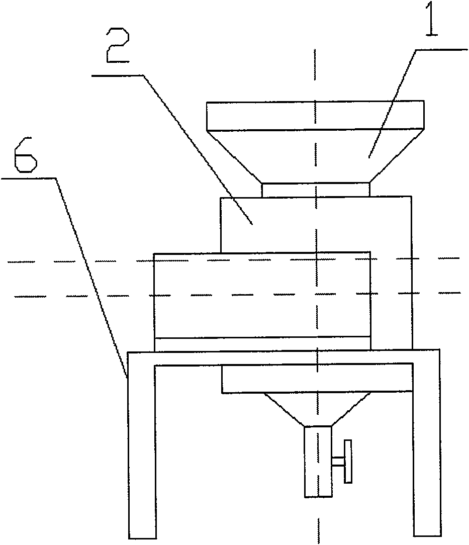
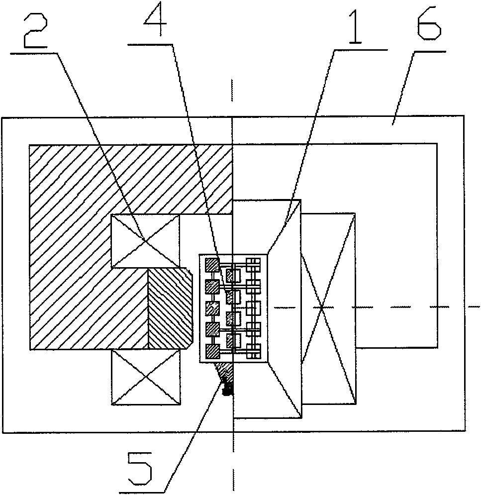
[0017] Refer to attached figure 1 , figure 2 , image 3 , The present invention includes feeding tank 1, electromagnet 2, magnetic separation tank 3, magnetic medium 4, ultrasonic transducer 5, bracket 6. The feed tank 1 is made of non-magnetic stainless steel and has a rectangular shape; the electromagnet 2 is a C-shaped electromagnet, which is fixed horizontally on the bracket 6, and its magnetic poles are made of iron-cobalt alloy, with a cross-sectional area of 10×20cm 2 , The pole spacing is 5cm. The magnetic separation tank 3 vertically passes through the pole gap of the electromagnet 2 and is made of non-magnetic stainless steel plate. The magnetic medium 4 is filled in the magnetic separation tank 3, which is a frame structure composed of silicon steel strips arranged vertically, see the attached Figure 4 , the silicon steel strips are arranged at equal intervals in the frame, the upper and lower ends are fixed with steel plates, and the frame structure occupie...
Embodiment 2
[0020] Refer to attached figure 1 , figure 2 , image 3 , The present invention includes feeding tank 1, electromagnet 2, magnetic separation tank 3, magnetic medium 4, ultrasonic transducer 5, bracket 6. The ore feeding tank 1 and the magnetic separation tank 3 are made of aluminum plate, with a rectangular shape; the electromagnet 2 is a C-shaped electromagnet, which is fixed horizontally on the bracket 6, and the magnetic pole is made of iron-nickel alloy, with a cross-sectional area of 10×15cm 2 , The pole spacing is 6cm. The magnetic medium 4 is filled in the magnetic separation tank 3, which is a frame structure composed of magnetic steel rods arranged horizontally, and the two ends of the steel rods are fixed with aluminum plates, see the attached Figure 5 , The volume occupied by the magnetic separation tank is 15%. The ultrasonic transducer 5 is a PZT piezoelectric ceramic transducer with a frequency of 45kHz and a power of 60W. Its radiation surface is fixed ...
PUM
 Abstract
Description
Claims
Application Information
 - R&D Engineer
- R&D Manager
- IP Professional
- Industry Leading Data Capabilities
- Powerful AI technology
- Patent DNA Extraction
Browse by: Latest US Patents, China's latest patents, Technical Efficacy Thesaurus, Application Domain, Technology Topic, Popular Technical Reports.
© 2024 PatSnap. All rights reserved.Legal|Privacy policy|Modern Slavery Act Transparency Statement|Sitemap|About US| Contact US: help@patsnap.com