Filtration irrigation device

A technology of infiltration irrigation and porous filter membrane, applied in the direction of spraying device, spraying device, watering device, etc., can solve the problems of block cleaning, fast speed, fast impurity speed, etc., and achieve the effect of prolonging the service life

Inactive Publication Date: 2009-10-07
诸钧
View PDF0 Cites 14 Cited by
  • Summary
  • Abstract
  • Description
  • Claims
  • Application Information

AI Technical Summary

Problems solved by technology

The radial outlet water flow is perpendicular to the parallel water flow flowing in the pipe, and the parallel water flow also forms a certain shear force. However, due to the fast speed of the radial outlet water flow, the impurity speed is also fast, and the position of the outlet

Method used


Image

  • Filtration irrigation device
  • Filtration irrigation device
  • Filtration irrigation device

Examples


Embodiment 1

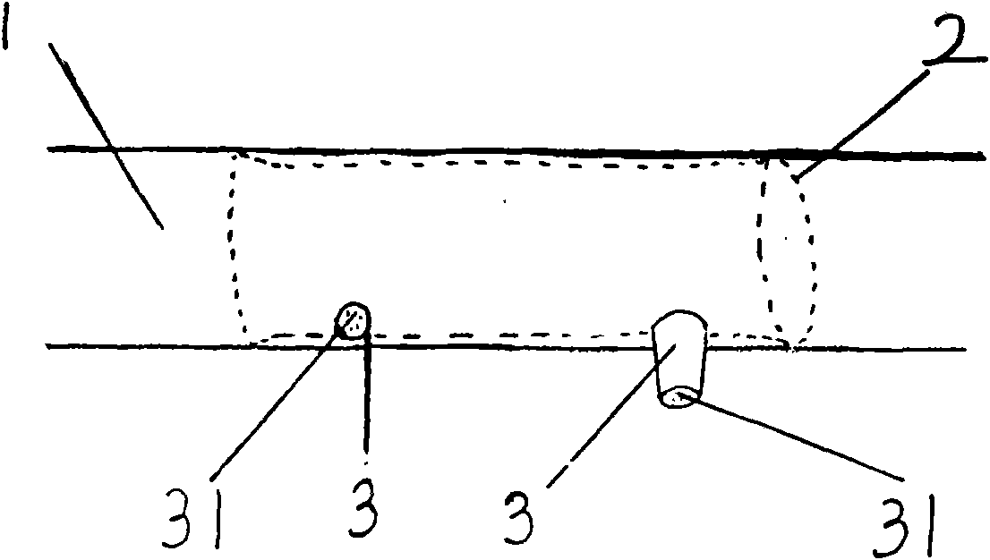
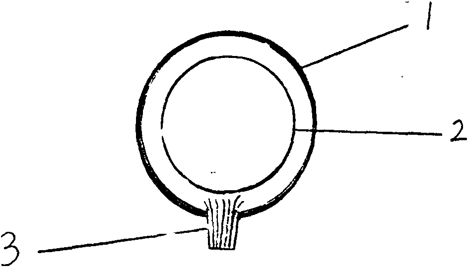
[0017] Such as figure 1 , figure 2 Shown, a kind of permeation irrigation device comprises tubular shell 1 and the porous filter membrane 2 that covers on the inner wall of tubular shell 1, the limited flow hole 31 in the restrictor 3 on the tubular shell 1 communicates with the inside and outside of tubular shell 1, porous filter The edge part of the membrane 2 is tightly sealed with the inner wall of the tubular shell without water leakage, and the water can only flow out of the percolation irrigation device after passing through the porous filter membrane 2 and the restrictor hole 31 in the restrictor 3, and become irrigation water. The restrictor 3 consists of one or several restrictor holes. The flow restrictor 3 can be directly opened on the pipe wall within the coverage of the porous filter membrane, or the flow restrictor can be extended to the outside of the infiltration irrigation device by extending the flow restrictor. Multiple flow restrictors can distribute ir...

Embodiment 2

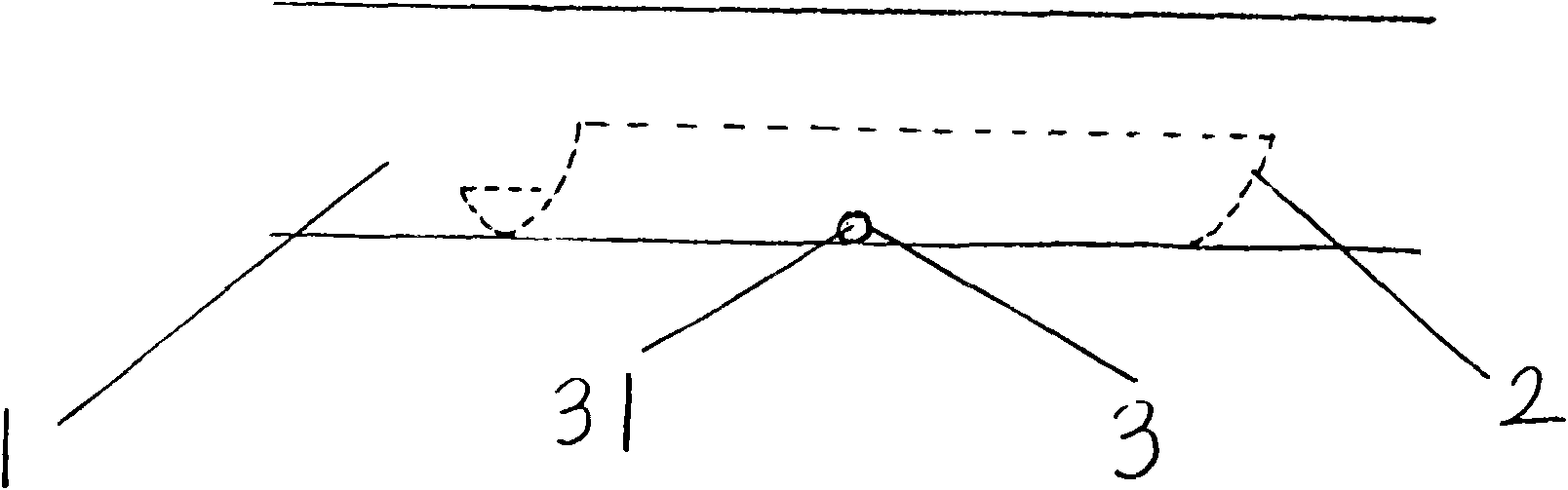
[0019] as figure 1 The change, image 3 , Figure 4 The porous filter membrane of the medium infiltration irrigation device only covers a small part of the infiltration irrigation device. The porous filter membrane 2 has a pore size of less than 10 microns, and its peripheral edge is closely connected with the inner wall of the tubular shell. Only when the flow-limiting hole 31 in the device 3 flows out can it become irrigation water, and the water flow in the tubular shell plays the role of cleaning up impurities when flowing through the surface of the porous filter membrane. The pore diameter of the flow restrictor is larger than that of the porous filter membrane, and its water seepage capacity is smaller than that of the porous filter membrane.

Embodiment 3

[0021] as image 3 further changes in Figure 5 The porous filter membrane 2 of the middle infiltration irrigation device is placed in the protruding external shell 12 on the tubular shell 1 , and the water outlet end of the external shell 12 is connected with the flow restrictor 3 . The external casing 12 communicates with the tubular casing 1, and part of the water in the tubular casing 1 enters the external casing 12, passes through the porous filter membrane 2, then enters the restrictor hole 31 in the restrictor 3, and then flows out to become irrigation water. The water flow in the tubular housing 1 has a cleaning effect on the impurities on the porous filter membrane 2 doing Brownian motion.


PUM

PropertyMeasurementUnit
Apertureaaaaaaaaaa
Apertureaaaaaaaaaa

Abstract

A filtration irrigation device consists of a tubular housing, a porous filter membrane and a flow snubber. Water in the tubular housing becomes irrigation water after passing through the porous filter membrane and the flow snubber sequentially. The porous filter membrane selects impurity grains having stronger pedesis characteristic as possible obstruction to be suspended on pores of the porous filter membrane, meanwhile, the flow snubber restricts extremely low flow velocity penetrating the porous filter membrane, so that the obstruction can only be suspended on the surface of the porous filter membrane; water flowing in the tubular housing plays a role of cleaning the obstruction on the surface layer of the porous filter membrane which can not be blocked for long-time use; the aperture of a limiting hole in the flow snubber is greater than the aperture of the porous filter membrane, so that the flow snubber can not be blocked. The filtration irrigation device can be used for a long time without being blocked.

Description

technical field [0001] The invention relates to a seepage irrigation device. Background technique [0002] One of the biggest problems encountered in today's drip irrigation and infiltration irrigation is the blockage of the water outlet of the emitter. In order to prevent blockage, the current common practice is to carry out water treatment at the water supply end of the irrigation pipe network, which not only requires a large investment in equipment costs, but also causes the entire pipe network to be scrapped due to improper water treatment. [0003] After research, it is found that the outlet aperture of drip irrigation is mostly between 0.2-1mm, and the main outlet aperture of seepage irrigation is from tens of microns to more than one hundred microns. The impurity particles that cause blockage are also many impurities with different diameters in the above aperture range As a result of co-sedimentation, particle diameters range from tens of microns to less than a micro...

Claims


Application Information

Patent Timeline
IPC IPC(8): B05B1/20
CPCA01G25/023Y02A40/22
Inventor 诸钧
Owner 诸钧
Why Eureka
Try Eureka