Driving device for manufacturing underground continuous wall and jointing method

A technology for underground diaphragm walls and driving devices, applied in sheet pile walls, underwater structures, water conservancy projects, etc., can solve problems such as low shear resistance, high cost, and poor integrity, and achieve strong digital selectivity and applicable Wide-ranging, quality-assured effects

Inactive Publication Date: 2009-10-07
王毅
View PDF0 Cites 2 Cited by
  • Summary
  • Abstract
  • Description
  • Claims
  • Application Information

AI Technical Summary

Problems solved by technology

Poor rigidity Poor integrity
Low shear resistance, easy to deform after being stressed, poor anti-seepage and water-proof performance
The joint structure of the joint box is complex, and there are many construction procedures, which brings difficulties to the installation of the reinforcement cage in the next trough on the brush wall
∪-shaped joint pipes and slide-type joint boxes have complex procedures, require a large amount of joint steel plates, and are expensive

Method used


Image

  • Driving device for manufacturing underground continuous wall and jointing method
  • Driving device for manufacturing underground continuous wall and jointing method
  • Driving device for manufacturing underground continuous wall and jointing method

Examples


Embodiment Construction

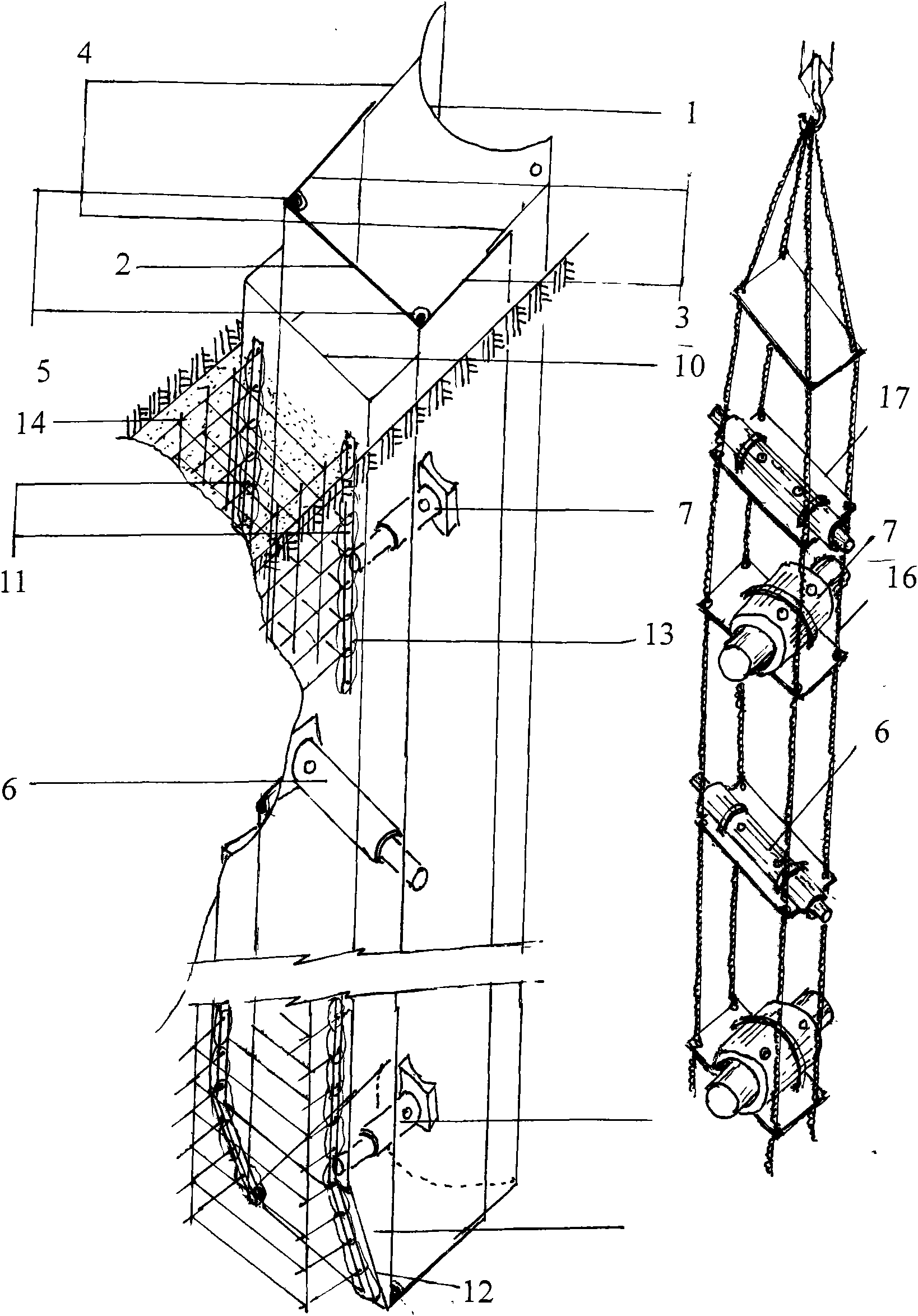
[0031] Such as figure 1 The hydraulic drive unit is shown in the figure

[0032] (A) The supporting plate 3 and the blocking plate 2 are formed into a [shaped structure by the shaft 5.

[0033] (B) The support plate 3 is vertically supported on the groove wall around the axis 5 after the hydraulic cylinder 6 works

[0034] (C) The hydraulic cylinder 7 supports the blocking plate 2 and the meniscus device to force the rotary drill to rotate

[0035] (D) The groove wall is unstable and the meniscus device pulls the sliding plate 4 enclosure

[0036] (E) After the hydraulic cylinder 6 is retracted, the hydraulic cylinder 7 is retracted to force the [shaped structure to move forward.

[0037] (F) Hydraulic cylinders 6 and 7 can also be hoisted into the [shaped structure by means of rope 16, bracket 17, effective digits in series, respectively, depending on the working conditions.

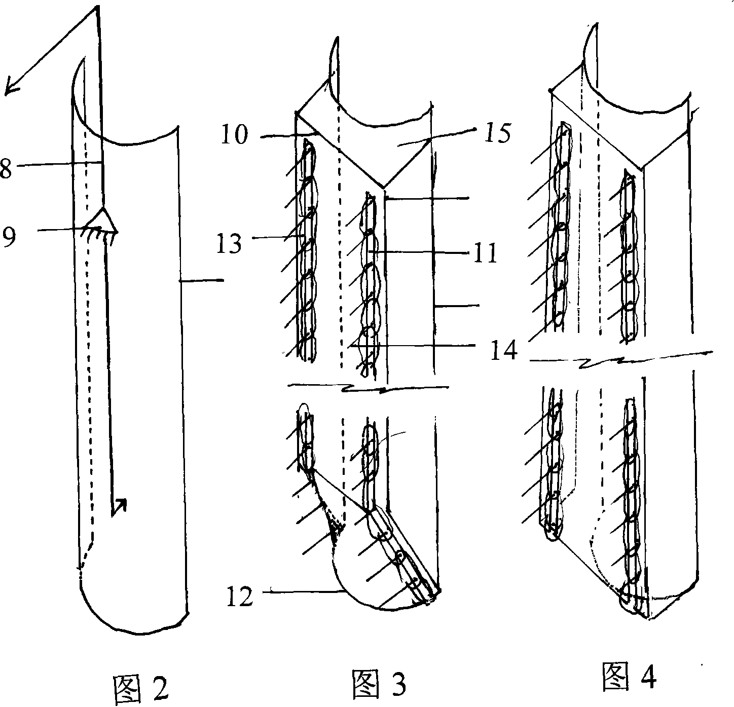
[0038] Such as figure 2 The lever support is shown in the diagram

[0039] (A) The fulcrum 9 ...


PUM


Abstract

The invention relates to a driving device for manufacturing an underground continuous wall and a jointing method, which belong to the field of underground continuous wall construction. One driving method is as follows: a hydraulic cylinder 6 works, a vertical supporting plate 3 is used for supporting a slot wall around an axle 5, and a hydraulic cylinder 7 works to support a blocking plate 2 to drive a semilunar plate device 1 to move to cause a traveling drill to travel; and the other driving method is as follows: a fixed pivot 9 of a lever 8 is placed on a working machine, a semilunar plate is driven to enable the traveling drill to be forced to travel under the action of force, as for the joining method I: a horizontal reinforcing bar is left at the position where an inserting plate 10 with a socket 11 penetrates through the end of a horizontal concrete bar 14, a gap is sealed by a metal sheet 13, and in the process of hoisting, vibrating and sinking after assembly, the self-compacting concrete is poured according to working conditions, and as for the joining method II ; a scraping head 12 of the inserting plate enables the composite material to be separated from the scraping head 12 along the semilunar plate 1 to form a cavity 15. The underground continuous wall can be encircled into closed joints by adopting inserting type angle joints or overlapped straight joints. The invention effectively solves the problems of difficult and focal points and pollution of the underground continuous wall and promotes the underground continuous wall to develop well and rapidly.

Description

technical field [0001] The invention belongs to the field of underground engineering construction, in particular to a driving device and a joint method in an underground continuous wall. Background technique [0002] Rotary drilling needs to form holes at intervals in the direction of grooves to loosen in case of harder soil or deeper. The joint treatment of the underground diaphragm wall is the key and difficult point in the construction of the diaphragm wall, and it is also the weak link of the diaphragm wall. The joint formation of the continuous wall and the selection of joint equipment directly affect the joint quality of the continuous wall. Such as joint pipe (also known as lock pipe) joint. Poor rigidity and poor integrity. The shear resistance is low, it is easy to deform after being stressed, and the anti-seepage and water-proof performance is poor. The joint structure of the joint box is complicated, and there are many construction procedures, which bring diff...

Claims


Application Information

Patent Timeline
IPC IPC(8): E02D5/18E02F5/02E02D29/02
Inventor 王毅王剑王英权姜璞王心丹
Owner 王毅
Why Eureka
Try Eureka