Eureka AIR delivers breakthrough ideas for toughest innovation challenges, trusted by R&D personnel around the world.

Adjustment and installation device for optical antenna of semiconductor laser range instrument

A technology of laser range finder and optical antenna, applied in the field of optical calibration, can solve the problem of cumbersome installation and adjustment process, great influence on installation and adjustment accuracy, and no calibration method or calibration process of semiconductor laser range finder optical antenna. problems, to achieve the effect of simple installation, high adjustment accuracy and high efficiency

Active Publication Date: 2009-10-07
NANJING UNIV OF SCI & TECH
View PDF1 Cites 27 Cited by
  • Summary
  • Abstract
  • Description
  • Claims
  • Application Information

AI Technical Summary

Problems solved by technology

In this method, the emission spot on the focal plane of the collimator needs to be found first, and a small hole is set at the emission spot. At the same time, an external light source is used to illuminate the small hole to form a reference beam for receiving antenna adjustment. Therefore, the installation and adjustment process is cumbersome. And the adjustment accuracy is greatly affected by the size, position and lighting source of the small hole
In addition, in the existing literature, there is no report on the "correction method for the optical transmission and reception field of view of the laser rangefinder", let alone the "complete calibration method or calibration process of the optical antenna of the semiconductor laser rangefinder". to report

Method used


Image

  • Adjustment and installation device for optical antenna of semiconductor laser range instrument
  • Adjustment and installation device for optical antenna of semiconductor laser range instrument

Examples


Embodiment Construction

[0011] The present invention will be further described below in conjunction with the accompanying drawings.

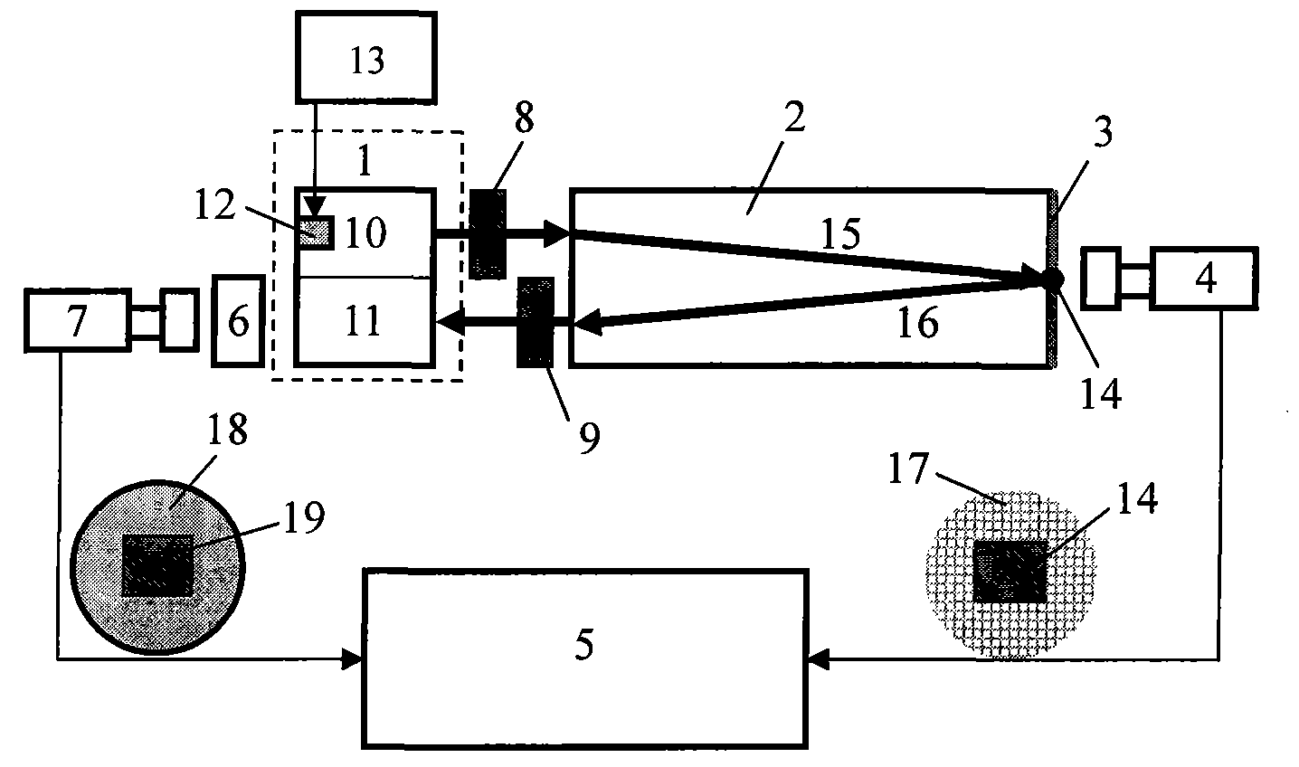
[0012] combine figure 1 , the calibration device of semiconductor laser rangefinder optical antenna of the present invention, it is characterized in that collimator 2 is set after being schooled optical antenna 1; The focal plane of this collimator 2 is set image screen 3; After the screen 3, a rear-end area-array CCD camera 4 is set; the area-array CCD camera 4 is connected to a computer 5; before the optical antenna 1 is adjusted, a reading microscope 6 is set; on the reading microscope 6, a front-end area-array CCD camera is connected 7; the area array CCD camera 7 is connected with the computer 5; the schooled optical antenna 1 includes a transmitting antenna 10 and a receiving antenna 11, and a semiconductor laser 12 is installed on the transmitting antenna 10; the semiconductor laser 12 on the transmitting antenna 10 and the driving power supply 13 connected.

...


PUM


Abstract

The invention discloses an adjustment and installation device for an optical antenna of a semiconductor laser range instrument. A parallel light tube is arranged behind the adjusted optical antenna; an image screen is arranged on a focus surface of the parallel light tube; a rear end area array camera is arranged behind the image screen; the rear end area array camera is connected with a computer; a reading microscope is arranged before the adjusted optical antenna; the reading microscope is connected with a front end area array CCD camera which is connected with the computer; the adjusted optical antenna comprises a transmitting antenna and a receiving antenna; and a semiconductor laser is arranged on the transmitting antenna and connected with a driving power. The adjustment and installing device can achieve integrated and visualized accurate optical antenna adjustment and installing with laser shot, viewing filed receiving and optical axle parallelity, has the advantages of simple structure, high optical antenna installation and adjustment precision and efficiency, no influence by subjective factors, and the like, and can be widely applied to the adjustment and the installation of the optical antenna of the semiconductor laser range instrument.

Description

technical field [0001] The invention relates to an optical calibration technology, in particular to an optical antenna calibration device for a semiconductor laser range finder. Background technique [0002] Laser ranging technology is an active remote sensing technology. It is widely used in important fields such as range testing, laser aiming, geodetic surveying, engineering construction, and water and soil monitoring. It is an important dual-use technology for both military and civilian purposes. [0003] The basic principle of the laser ranging system is "to launch a detection laser to the target, then receive the echo scattered by the target, and obtain the distance information of the target through the analysis of the echo". Usually, in order to achieve the largest possible detection distance, the divergence angle of the detection beam should be compressed to a minimum to ensure the directional propagation of energy. Correspondingly, in order to improve the signal-to-...

Claims


Application Information

Patent Timeline
IPC IPC(8): G01S7/497G01S17/08
Inventor 来建成李振华王春勇姜海娇
Owner NANJING UNIV OF SCI & TECH
Why Eureka
Eureka Blog
Learn More