Transverse flux cylinder type permanent magnet linear synchronous motor

A permanent magnet linear synchronous, transverse magnetic flux technology, applied in electrical components, electromechanical devices, electric components, etc., can solve problems such as the dynamic characteristics of the motor affecting the current control accuracy, the low efficiency of the linear synchronous motor, and the large eddy current loss of the solid iron core. Achieve the effect of improving the accuracy and efficiency of current and electromagnetic force control, simple structure and improving efficiency

Inactive Publication Date: 2009-10-07
HARBIN INST OF TECH
View PDF0 Cites 27 Cited by
  • Summary
  • Abstract
  • Description
  • Claims
  • Application Information

AI Technical Summary

Problems solved by technology

[0003] The present invention solves the problems of low efficiency, large eddy current loss, complex laminated iron core process and high processing cost of the existing linear synchronous motor; larger eddy current loss in the

Method used


Image

  • Transverse flux cylinder type permanent magnet linear synchronous motor
  • Transverse flux cylinder type permanent magnet linear synchronous motor
  • Transverse flux cylinder type permanent magnet linear synchronous motor

Examples


specific Embodiment approach 1

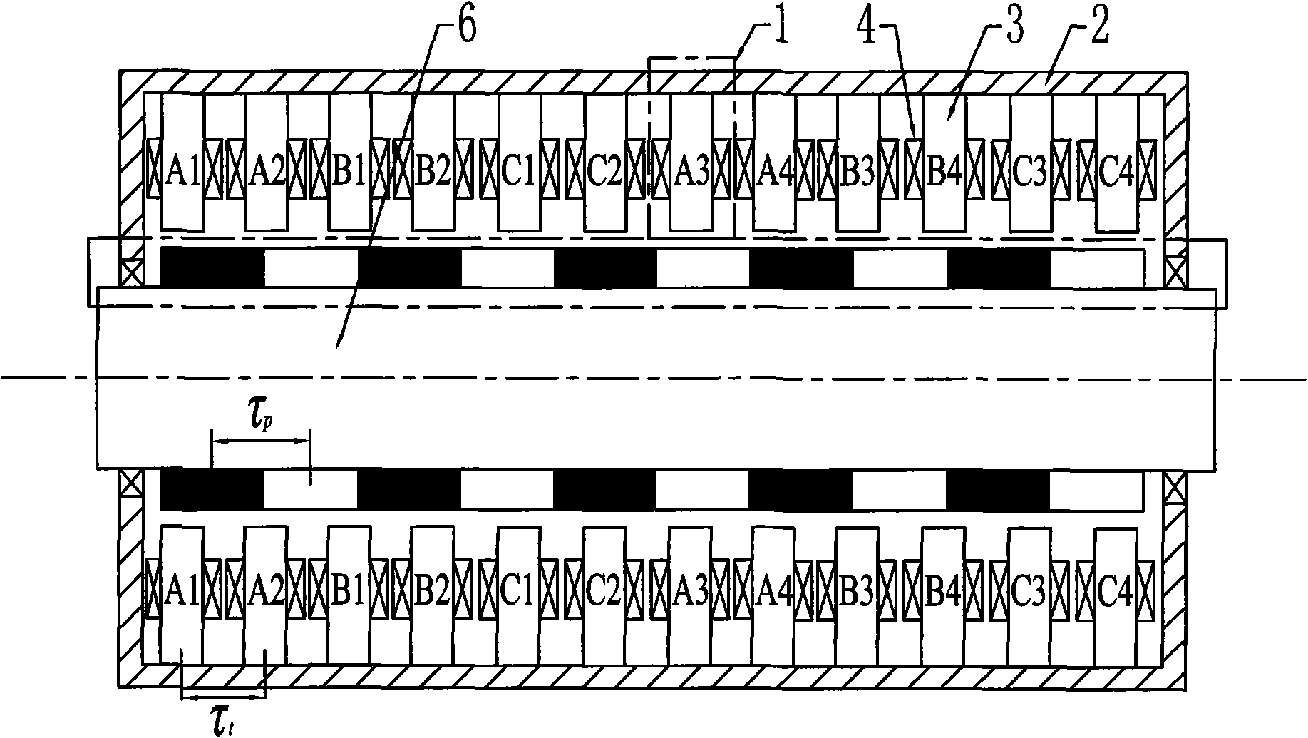
[0013] Specific implementation mode one: combine figure 1 and figure 2 This embodiment will be described. The transverse flux cylindrical permanent magnet linear synchronous motor of this embodiment is composed of a primary, a secondary and an air gap; the primary includes S phase armature units 1 and a casing 2, where S=nm, S phase armature units 1 Arranged on the inner wall of the casing 2; the phase armature unit 1 includes the phase unit armature core 3 and the phase unit armature winding 4, and the winding directions of the coils on the adjacent phase unit armature core 3 are opposite; each phase unit armature The core 3 is a ring core with 2q teeth uniformly arranged on the inner circumference, the phase unit armature winding 4 is a concentrated winding, and a coil is wound on each tooth of the phase unit armature core 3, and the coils on the adjacent teeth are wound in the direction of On the contrary, all the coils on the teeth of the same phase unit armature core ...

specific Embodiment approach 2

[0019] Embodiment 2: This embodiment differs from Embodiment 1 in that the shaft cylinder 6 is cylindrical or cylindrical; the shaft cylinder 6 is made of magnetically conductive or non-magnetically conductive material. Other compositions and connection methods are the same as those in Embodiment 1.

specific Embodiment approach 3

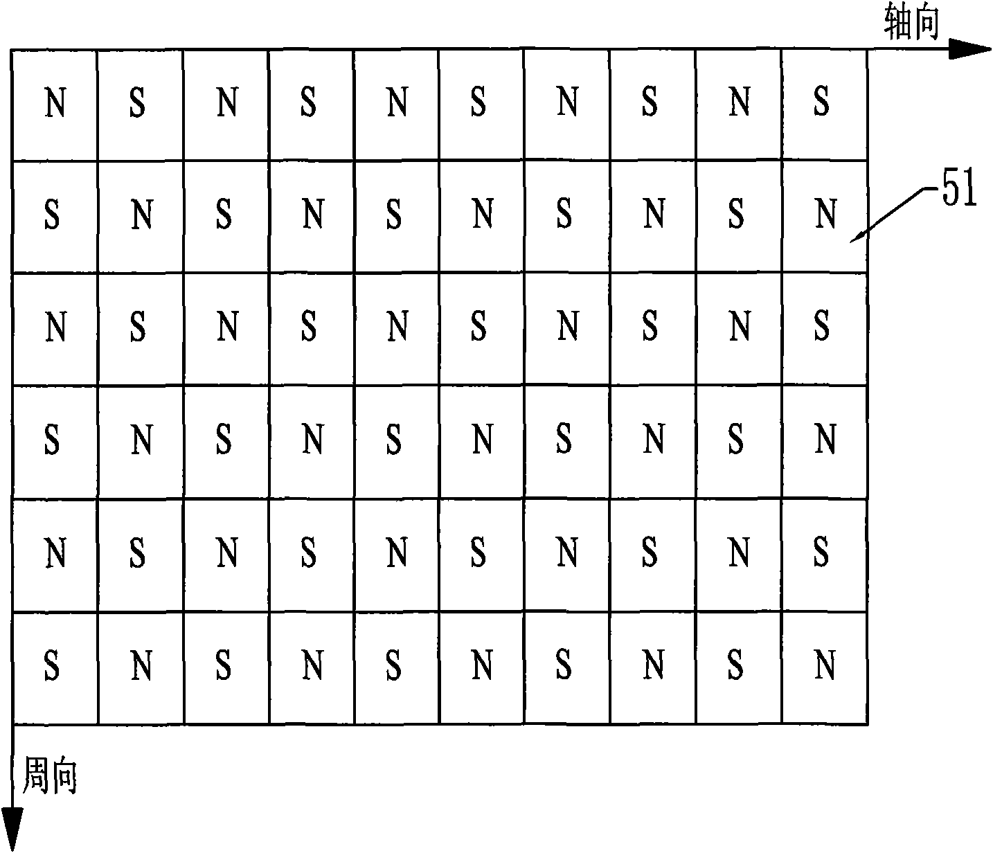
[0020] Specific implementation mode three: combination image 3 Describe this embodiment, the difference between this embodiment and the specific embodiment is that the permanent magnet array is composed of tile-shaped permanent magnets 51, and the magnetization direction of the tile-shaped permanent magnets 51 is radial magnetization, and the plurality of tiles Shaped permanent magnets 51 are adjacently arranged to form a permanent magnet circle along the circumferential direction, and 2q permanent magnet circles are arranged adjacent to each other along the axial direction, and the magnetization direction of every adjacent two tile-shaped permanent magnets 51 is opposite.

[0021] The permanent magnet array described in this embodiment is made up of tile-shaped permanent magnets 51, and each N-pole tile-shaped permanent magnet is surrounded by 4 S-pole tile-shaped permanent magnets, and each S-pole tile-shaped permanent magnet is also surrounded by Surrounded by 4 N-pole til...


PUM


Abstract

A transverse flux cylinder type permanent magnet linear synchronous motor relates to the field of motor, and settles the problems of low efficiency, large eddy current loss, complex technique and effect to the control precision and dynamic characteristic. The transverse flux cylinder type permanent magnet linear synchronous motor of the invention comprises a primary stage, a secondary stage and an air gap. The number of phase armature units is S=nm, wherein n is a natural number. The number of axial magnetic poles formed by secondary permanent magnets is P=2i, wherein is a natural number. When no common divisor exists between S and P, the S phase armature units are equally divided to m groups along the axial direction, and each n adjacent phase armature units belong to one phase. When a highest common divisor j exists between S and P, the S phase armature units are equally divided into mj parts along the axial direction, and windings on each adjacent n/j phase armature units belong to one phase. The phase unit armature core tooth pitch taut between two adjacent phase armature units along the axial direction and the pole distance taup along the axial permanent magnet satisfy a relationship mktaut=(mk+/-1)taup, wherein m and k are natural numbers, and m is the phase number of motor. The motor not only can be used as an electric motor, but also can be used as a generator.

Description

technical field [0001] The invention relates to motor technology, in particular to a cylindrical permanent magnet linear synchronous motor. Background technique [0002] The structure of the existing longitudinal flux cylindrical permanent magnet linear synchronous motor is as follows: Figure 10 shown. When the armature core is made of silicon steel sheets, since the direction of the laminations is axial, the direction of the armature magnetic field generated by the permanent magnet and the winding is partly in the same direction as the laminations, forming a large eddy current in the core, resulting in a larger Large eddy current loss, and the iron core lamination process is complicated, and the processing cost is high; if a solid iron core is used, although the process is simple and the cost is low, the iron core will generate greater eddy current loss, which greatly reduces the efficiency of the motor. At the same time, due to the existence of magnetic coupling between ...

Claims


Application Information

Patent Timeline
IPC IPC(8): H02K41/03
Inventor 寇宝泉谢大纲张鲁张赫
Owner HARBIN INST OF TECH
Why Eureka
Try Eureka