Design method of ultra-thin lens used for LED

A design method and technology of LED light source, applied in lighting and heating equipment, components of lighting devices, semiconductor devices of light-emitting elements, etc., can solve problems such as affecting the use of lenses, increasing light loss, etc. Astigmatism reduction effect

Active Publication Date: 2009-10-21
SHANGHAI SANSI ELECTRONICS ENG +3
View PDF0 Cites 19 Cited by
  • Summary
  • Abstract
  • Description
  • Claims
  • Application Information

AI Technical Summary

Problems solved by technology

Although the Fresnel lens becomes thinner in terms of thickness, since the sawtooth is connected by line segments in the same direction, the surface formed by the multiple line segments is an optical "ineffective part", which is also the cause

Method used


Image

  • Design method of ultra-thin lens used for LED
  • Design method of ultra-thin lens used for LED
  • Design method of ultra-thin lens used for LED

Examples


Embodiment Construction

[0036] The design method of the ultra-thin lens for LED of the present invention will be described in more detail with reference to the accompanying drawings.

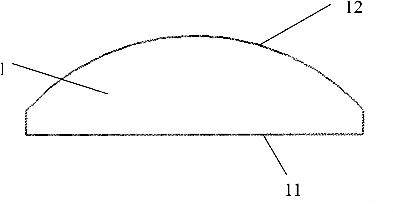
[0037] Such as figure 1 , first design the original lens 1 according to the specific optical requirements. In this embodiment, it is assumed that the incident surface 11 of the lens is a plane, and the outgoing surface 12 is assumed to be an ideal curved surface. As for how to design the shape of the original lens, it is not within the scope of the technical solution disclosed in the present invention. In this embodiment, the shape of the exit surface 12 is designed to achieve the purpose of thinning the lens.

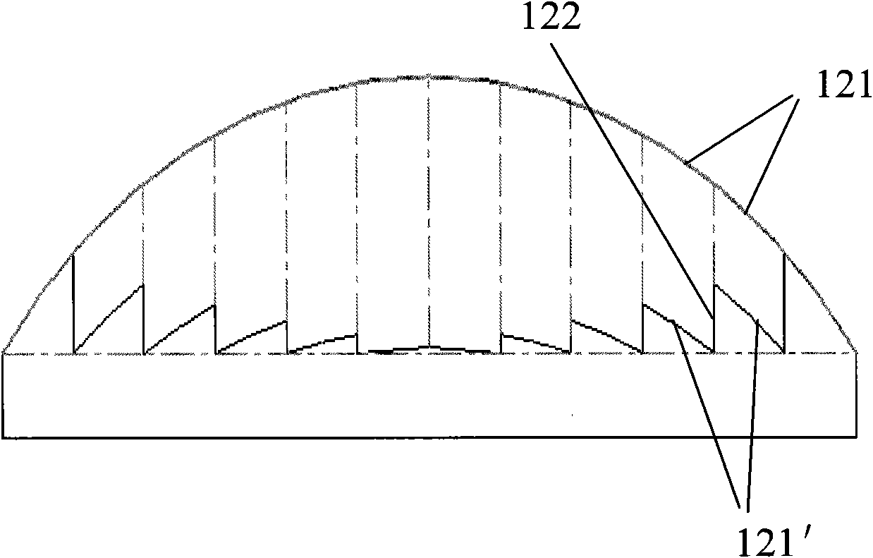
[0038] figure 2 is the prior art figure 1 A schematic diagram of a method for designing a section of the original lens 1 passing through the optical axis. The method is to first divide the exit surface 12 into a plurality of small curves 121, and then translate the multiple small curves 121 along the same...


PUM


Abstract

The invention relates to a design method of an ultra-thin lens used for an LED, relates to the optical field and solves the technical problem that the original lens changes from thick to thin. The method divides an incident face into a plurality of small sections of curves according to an opening angle thereof to a light source on the section of a light-passing axis of the original lens by adopting the located point of the LED light source as the center; all the points of the smaller sections of curves are moved along the corresponding incident ray; the length of the original incident ray in the moving process generates amplifying effect by preset proportion; the head part and the tail part of the small sections of adjacent curves after being amplified are connected along the straight line section of the ray direction so as to from a sawteeth section; and the sawteeth section rotates around the optical axis or be drawn along the direction of the normal line of the section so as to form a threaded or sawteeth sheet ultra-thin lens. The method not only can obtain the ultra-thin lens with any thickness and does not have influence on optical effect.

Description

technical field [0001] The invention relates to a design method of an optical element, more specifically, to a design method of changing an optical lens used for an LED from thick to thin. Background technique [0002] Optical components are very precise components, and the production cost is relatively high. However, due to the limitation of design methods, the thickness of common optical lenses is generally not made very thin. In this way, not only many optical materials are used, but the cost is high, and at the same time, due to the larger thickness, the absorption of light by the lens is increased, which reduces the utilization rate of light. Therefore, making optical lenses thinner and lighter has become one of the goals pursued by lens designers. [0003] Fresnel lens is a kind of thin lens, which has been widely used because of its lightness, thinness and low price. However, the common Fresnel lenses are mostly concentric circular structures with equal difference r...

Claims


Application Information

Patent Timeline
IPC IPC(8): F21V5/04H01L33/00F21Y101/02F21Y115/10
Inventor 陈必寿周士康陈鸣
Owner SHANGHAI SANSI ELECTRONICS ENG
Why Eureka
Try Eureka