
Long time domain signal processing device

A signal processing device and long-term technology, which is applied in the direction of beam guiding device, information storage, recording information storage, etc., can solve the problems of array resolvable change limitation and signal bandwidth limitation

Inactive Publication Date: 2009-10-21
UNIV OF ELECTRONICS SCI & TECH OF CHINA
View PDF2 Cites 0 Cited by
  • Summary
  • Abstract
  • Description
  • Claims
  • Application Information

AI Technical Summary

Problems solved by technology

The spatial distribution of diffracted light is time-varying, and the Nyquis sampling theorem limits the resolvable variation of the array
Therefore, the signal bandwidth that can be processed is limited

Method used


Image

  • Long time domain signal processing device

Examples


Embodiment Construction

[0020] The present invention will be further described below in conjunction with accompanying drawing:

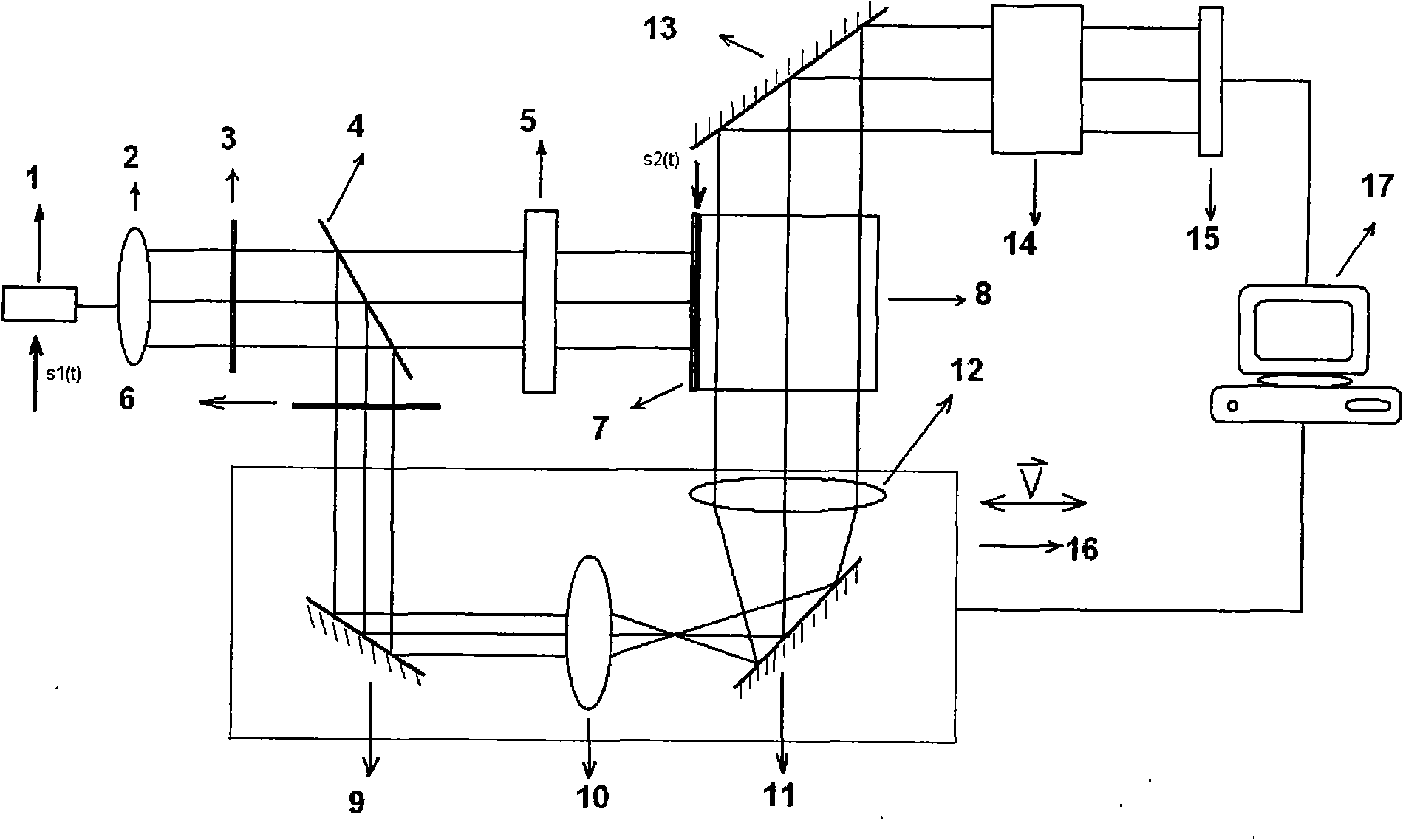
[0021] The structure of a device for realizing long-time domain signal processing proposed by the present invention is as follows: figure 1 As shown, it specifically includes a laser 1, a beam expander and collimator lens group 2, a wave plate 3, a semi-transparent lens 4, a spatial light modulator 5, a shutter 6, an acousto-optic Bragg element 7, an optical storage medium or an array 8 , mirror 9, first optical lens 10, mirror 11, second optical lens 12, mirror 13, imaging system 14, photoelectric detection array 15, precision translation stage 16 and computer 17.

[0022] Each component is placed on the optical platform, where the laser 1 is supplied with a certain bias voltage V 1 After that, use the received radio frequency electrical signal S 1 (t) modulate the laser, add a certain bias voltage V to the acousto-optic Bragg element 7 2 After that, use quasi-signal S ...


PUM


Abstract

The invention discloses a device for realizing long time domain signal processing. The device stores a Bragg acousto-optic relevant optical signal in an optical storage array and a storage medium through optical storage technology, and then reads the stored optical signal for signal processing. The technology aims to the technical field of the relevant operation of a long time domain signal. The device has the outstanding advantage that: the long time domain signal, particularly a signal with the time-bandwidth product more than 10 can be processed through the method.

Description

technical field [0001] The invention relates to the technical field of acousto-optic signal processing, in particular to a long-time-domain signal processing device. Background technique [0002] The fundamental advantage of acousto-optic signal processing technology is that it uses acousto-optic Bragg devices to quickly process electronic signal information. The core part of acousto-optic signal processing is Bragg devices. The piezoelectric transducer is used to convert the electrical signal to be measured or the reference signal into an acoustic signal to form a traveling wave grating, and the grating is used to diffract the incident optical signal modulated by the signal. Using the acousto-optic interaction, as well as the related optical path and photoelectric detection system, information processing such as correlation calculation of complex electrical signals can be realized. [0003] At the same time, the invention patent CN2314493Y "a space-integrated acousto-optic...

Claims


Application Information

Patent Timeline
Patent Type & Authority Applications(China)
IPC IPC(8): G11B7/0065G11B7/09G11B7/135G02F1/11G11B7/1372
Inventor 杨立峰周鹰王亚非万勇高椿明王占平
Owner UNIV OF ELECTRONICS SCI & TECH OF CHINA
Learn More