The invention provides a method for reducing
noise and
harmonic distortion due to unwanted reflection such as
Rayleigh scattering, reflections from other sensors multiplexed on the same
fiber, connectors, etc. The invention also provides a method that increases the threshold for Stimulated
Brillouin Scattering (SBS). This enables more
optical power to be launched into the optical network, when the
optical power of the source is limited by SBS. The reduction of
noise and
harmonic distortion and the increase of the SBS threshold are achieved by reducing the coherence of a highly coherent optical source by coherence modulation means that modulates the output field
phasor of each channel to produce a broadened optical source power spectrum.
The coherence modulation means reduces the autocorrelation of the source, where the autocorrelation function of a
wavelength channel is defined as the
Fourier transform of the optical source power spectrum in one
wavelength channel, where the
optical power spectrum is defined with a resolution bandwidth similar to the necessary detection bandwidth. Alternatively, the autocorrelation function of a
wavelength channel from the source versus delay may be defined as a
filter impulse response convolved with the product of the conjugate of output field phasor and the output field phasor delayed by the given delay, where the
filter impulse response has a frequency representation with a bandwidth similar to the necessary detection bandwidth. The
coherence time may be defined as the
full width at half maximum (FWHM) of the autocorrelation function. The
coherence time is inversely proportional to the bandwidth of the optical source power spectrum. An efficient coherence modulation means for use in combination with a compensating interferometer will produce an output field phasor with a
coherence time that is significantly shorter than the sensor delay. If the coherence time is sufficiently short, signal components that appear due to interference formed between optical pathways, with a delay different from the sensor delay of the interrogated interferometer, will be substantially suppressed. If a compensating interferometer is not used, significant improvements can still be achieved by reducing the coherence time from that of a highly coherent
laser source to a coherence time that is reduced but longer than the sensor interferometer delay, without disturbing the mean source frequency.
It is essential that the coherence modulation means produce an autocorrelation function that is stable versus time. If this is not the case, noise will be added on the signal from sensors with sensor delays that are not completely matched with the maximum of the autocorrelation function. The stability of the autocorrelation function within the necessary detection bandwidth can be achieved by modulating the output field phasor of each wavelength channel from the source in a periodic manner with a
cycle frequency that is larger than the necessary detection bandwidth. Alternatively, stability of the autocorrelation function can be achieved by modulation of the output field phasor of each wavelength channel from the source in a periodic manner with a
cycle frequency that is phase-locked to a
demodulation carrier frequency, such as the phase generated carrier (PGC) modulation frequency in a
system employing PGC
demodulation or the
heterodyne frequency in a
system employing
heterodyne demodulation.
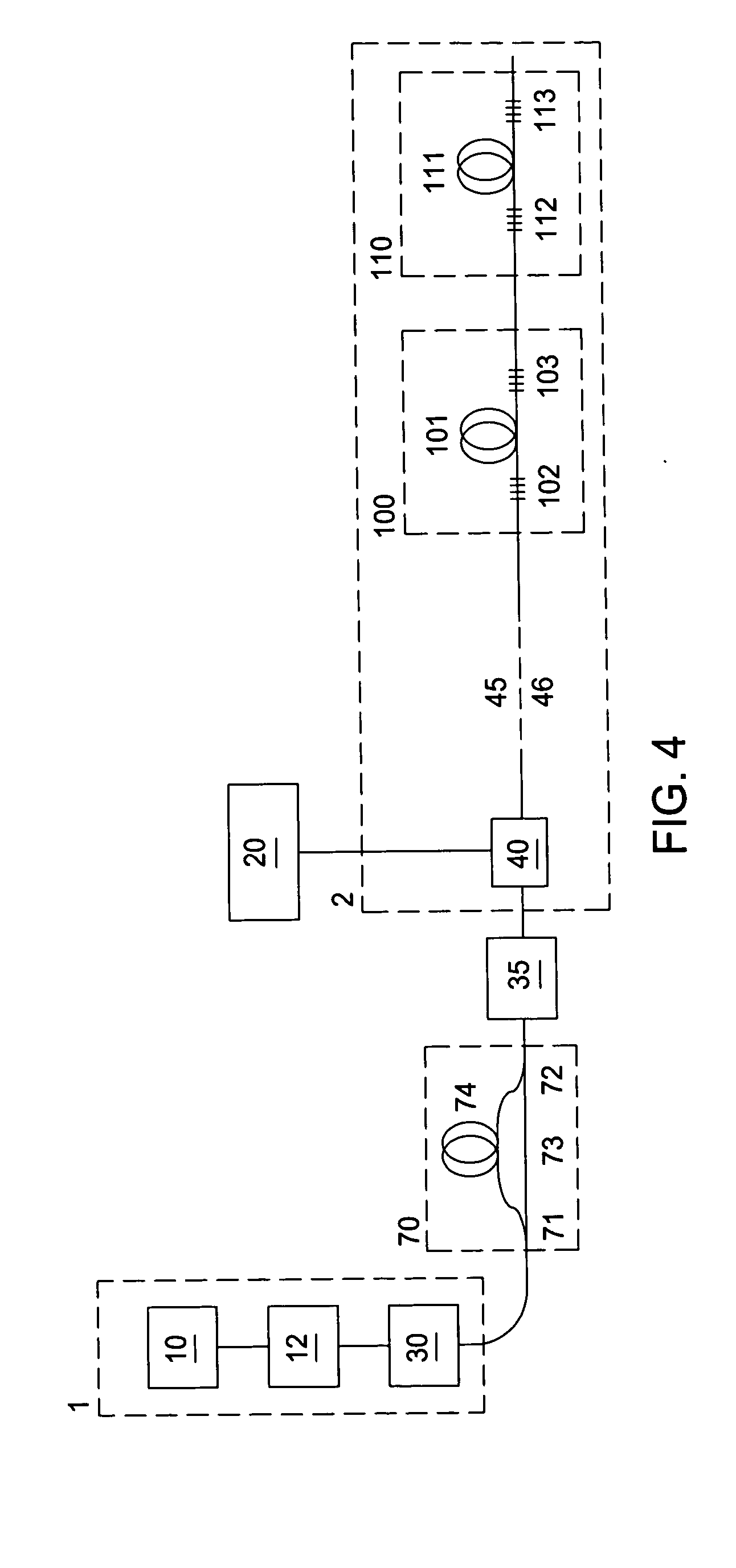
Coherence modulation means that produces a broadened optical spectrum may be achieved by direct modulation of the source
laser for each wavelength channel. If the source
laser is a
fiber laser, direct modulation can be achieved by periodic strain modulation of the
fiber laser. If the source laser is a
diode laser, direct modulation can be achieved by periodic modulation of the drive signal of the
diode laser, and the modulation signal may have triangular waveform. If the source laser is a wavelength tunable
diode laser, direct modulation can be achieved by periodic modulation of one or more control signals to the wavelength tunable diode laser, and the laser wavelength may have triangular waveform. A triangular waveform provides a more uniform spread of the optical spectrum than a pure sine modulation, and thus more confined peak in the coherence function with less sidelobes.
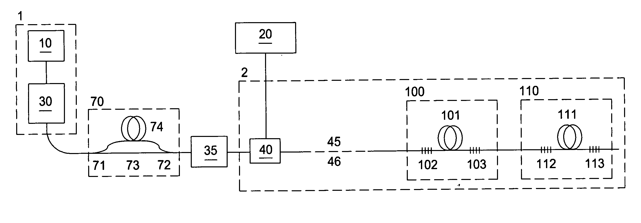
Coherence modulation means that produces a broadened optical spectrum may also be achieved by using an
optical modulator that takes light output from at least one coherent
light source as input and modulates the field phasor of the light before it is output from the modulator. Light from a multiple of coherent light sources operating at different
wavelength channels may be combined with a wavelength division
multiplexer and input to a common
optical modulator, which modulates all
wavelength channels simultaneously. This may provide a more cost
effective solution than to use one modulator for each wavelength source. The
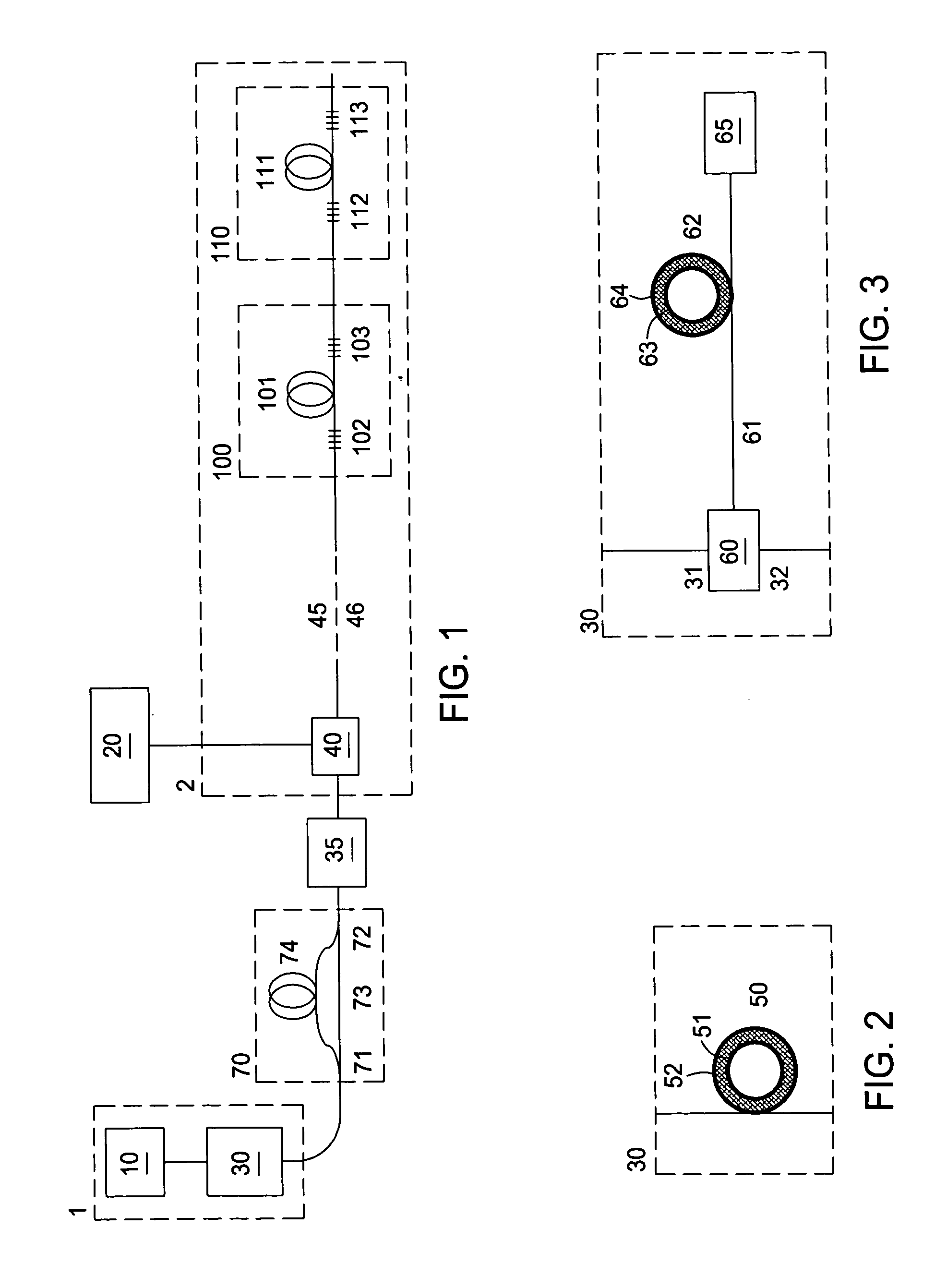
optical modulator may be one out of an
optical phase modulator, an optical amplitude modulator or an acousto-optical modulator. An
optical phase modulator may comprise an
optical fiber wound around a piezoelectric ring modulator, for example a
lead titanate zirconate (PZT) ring modulator. In order to reduce polarization effects, the
optical fiber may be twisted High
Birefringence fiber or polarization maintaining fiber, where the input polarization to the polarization maintaining fiber is polarized along one of the polarization maintaining fiber eigenaxes. The
optical phase modulator may also be an electro-optical phase modulator such as a
lithium niobate phase modulator.
Lithium niobate phase modulators have the
advantage of a much higher speed than most other types of optical modulators, and much shorter coherence lengths can therefore be achieved with such a device than with for example an acousto-optic modulator. The phase modulator may modulate the phase of the output field phasor of each wavelength channel with a repeated pseudorandom pattern switching between two phase-shift values that are separated by π radians. Other modulation patterns may also be employed. For a PZT ring modulator a sine modulation at a
mechanical resonance frequency of the PZT ring may be desirable.

