
Optical synchronization system for femtosecond x-ray sources

Active Publication Date: 2008-02-21
RGT UNIV OF CALIFORNIA
View PDF13 Cites 47 Cited by
  • Summary
  • Abstract
  • Description
  • Claims
  • Application Information

AI Technical Summary

Benefits of technology

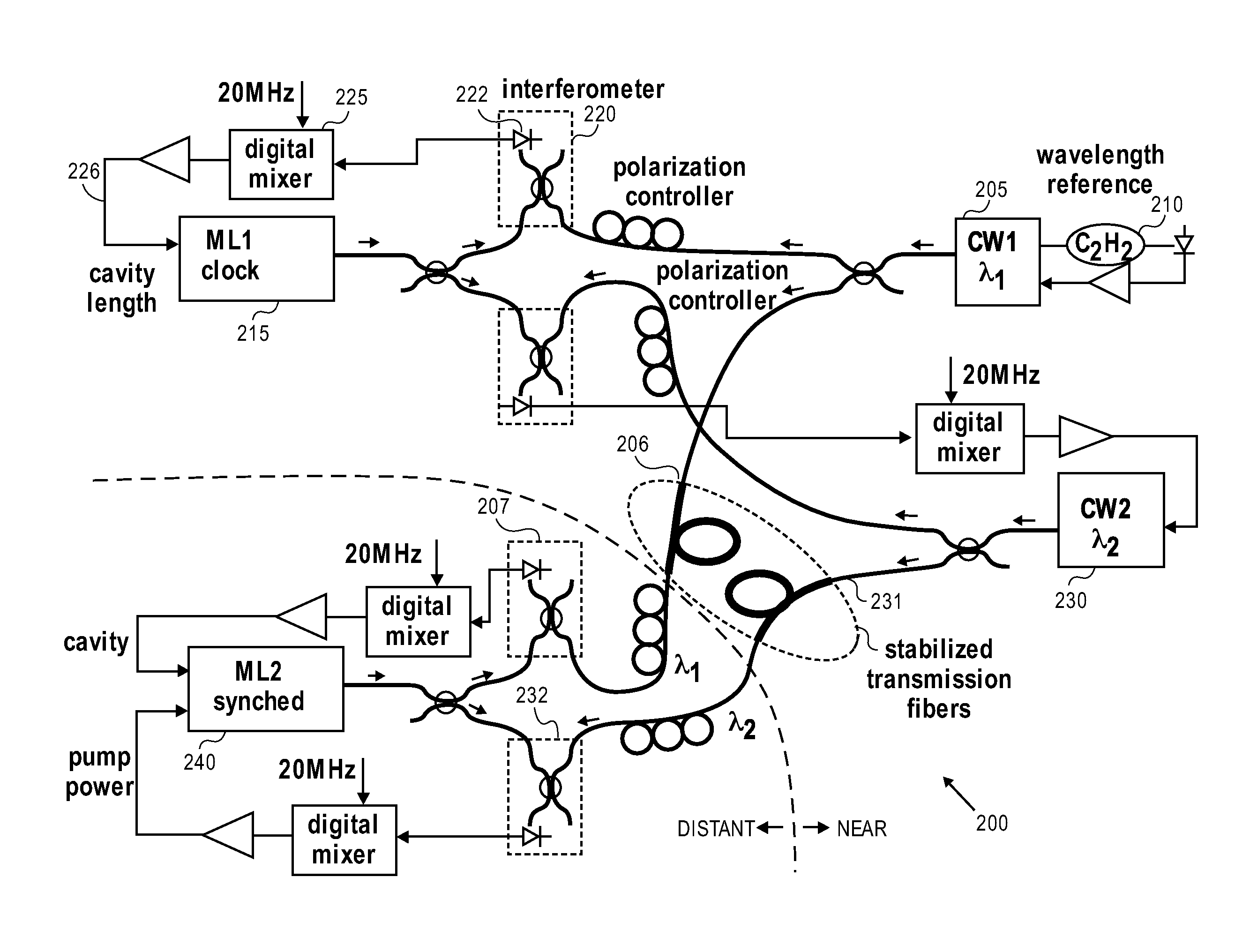
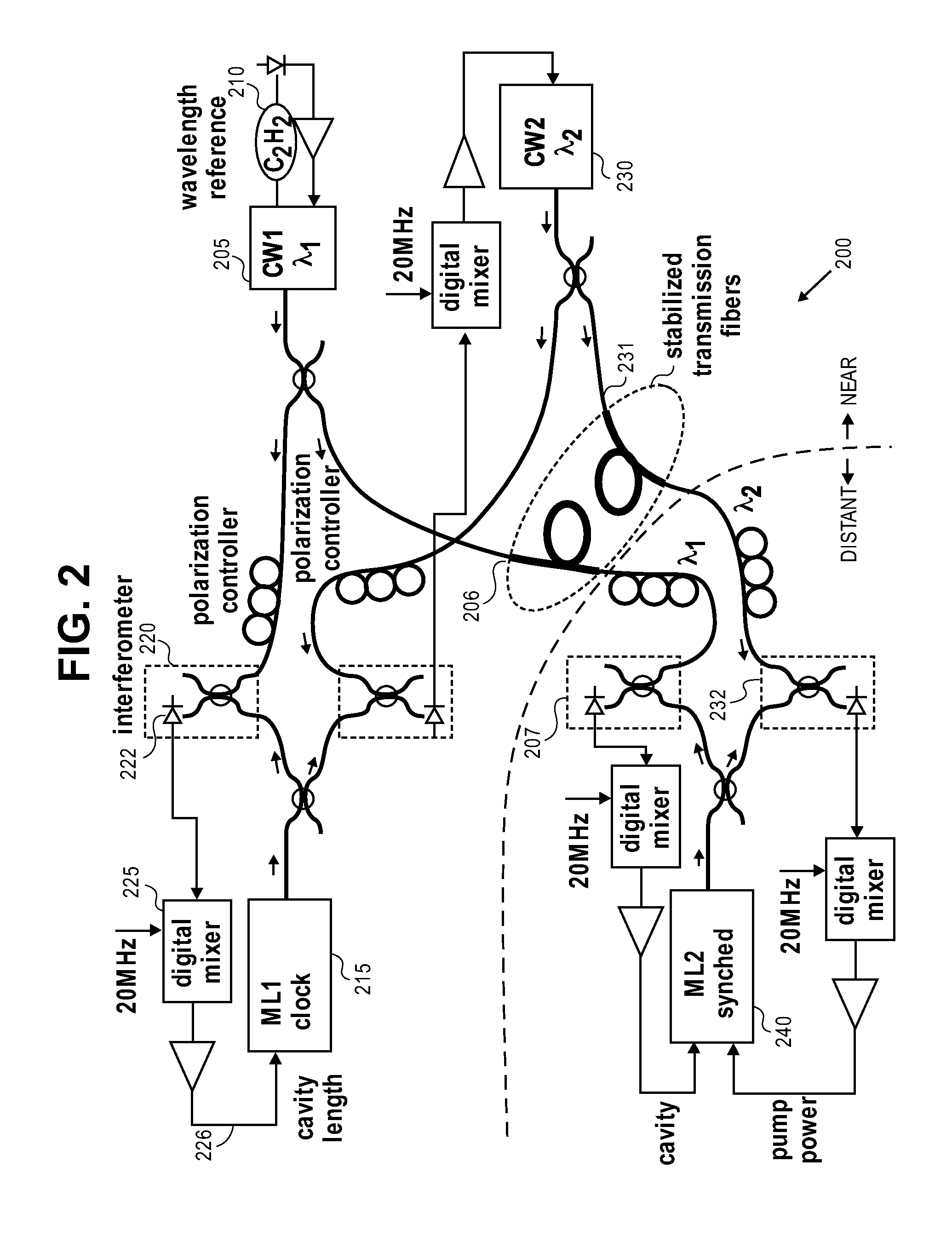
[0022] Once two frequencies that represent the timing information are generated, they must be transmitted. The preferred way to do this is via fiber optic, although they could be transmitted via free space beams or though other types of waveguides such as planar waveguides or lens waveguides. The transmitting medium must itself be stabilized in timing delay, and there is a preferred way to do this by using interferometric stabilization of an optical fiber. This method delivers accurate phase information to the end point, which is what is required. The stable single frequency to be transmitted is also used as a measurement of the phase delay through the transmitting optical fiber, by making the fiber one arm of an interferometer. The frequency is reflected from the receivin

Problems solved by technology

These methods have demonstrated low timing jitter between lasers, but have relative disadvantages.
Such transmission tends to broaden the pulses and distort temporal information.
Stabilization of the temporal delay in electrical cable is limited by phase detection of the RF signal to hundreds of femtoseconds, while transmission of RF over fiber requires optical-to-electrical conversion, which is unstable and susceptible to noise.
This may not be possible for many lasers that need to be synchronized to the sub-10 fs regime.

Method used


Image

  • Optical synchronization system for femtosecond x-ray sources
  • Optical synchronization system for femtosecond x-ray sources
  • Optical synchronization system for femtosecond x-ray sources

Examples


Embodiment Construction

Introduction

[0033] Synchronization of short pulse lasers to a high degree of accuracy (within a time scale measured in femtoseconds, 10−15 seconds) is important in various applications, including scientific experiments investigating short time scale phenomena. Several methods exist for sending timing information through optical fiber or coaxial cable in order to provide a synchronizing signal. These methods can be characterized as using either fast temporal modulation of a signal or interferometry. In either case, the degree of temporal synchronization is proportional to the frequency transmitted. Fiber optics can transmit much higher frequencies than coaxial cables and thus achieve higher precision synchronization, so most of the recent work in this area has been with fiber optics.

[0034] Using the fast temporal modulation method, some authors have reported fiber optic synchronization systems based on radio frequency (RF) modulation of a continuous wave (CW) laser, transmission th...


PUM


Abstract

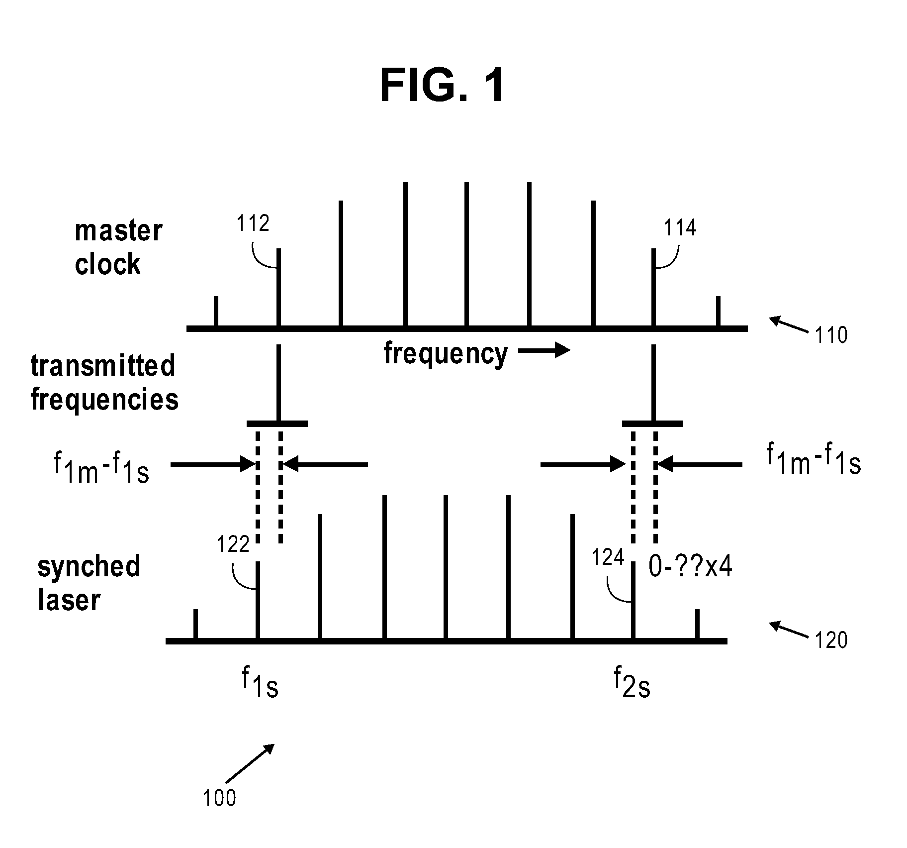
Femtosecond pump / probe experiments using short X-Ray and optical pulses require precise synchronization between 100 meter-10 km separated lasers in a various experiments. For stabilization in the hundred femtosecond range a CW laser is amplitude modulated at 1-10 GHz, the signal retroreflected from the far end, and the relative phase used to correct the transit time with various implementations. For the sub-10 fsec range the laser frequency itself is upshifted 55 MHz with an acousto-optical modulator, retroreflected, upshifted again and phase compared at the sending end to a 110 MHz reference. Initial experiments indicate less than 1 fsec timing jitter. To lock lasers in the sub-10 fs range two single-frequency lasers separated by several teraHertz will be lock to a master modelocked fiber laser, transmit the two frequencies over fiber, and lock two comb lines of a slave laser to these frequencies, thus synchronizing the two modelocked laser envelopes.

Description

CROSS-REFERENCE TO RELATED APPLICATIONS [0001] This application claims benefit of priority to U.S. provisional patent application 60 / 744,218 filed Apr. 4, 2006, entitled “Optical Synchronization System for Femtosecond X-ray Sources”, which is hereby incorporated by reference in its entirety.STATEMENT OF GOVERNMENTAL SUPPORT [0002] This invention was made during work supported by U.S. Department of Energy under Contract No. DE-AC02-05CH11231. The government has certain rights in this invention.REFERENCE TO SEQUENCE LISTING, TABLE, OR COMPUTER PROGRAM APPENDIX [0003] Not applicable. BACKGROUND OF THE INVENTION [0004] 1. Field of the Invention [0005] The present invention relates generally to synchronization, more specifically to synchronization of laser systems, and most specifically to synchronization of laser systems with femtosecond synchronization levels. [0006] 2. Related Art [0007] Previous methods of synchronization of pulsed lasers have employed transmission of short pulses, o...

Claims


Application Information

Patent Timeline
IPC IPC(8): H01S3/098
CPCH01S3/1394H01S3/1305H01S3/1307H01S3/2391
Inventor WILCOX, RUSSELL B.
Owner RGT UNIV OF CALIFORNIA
Learn More