Deep well gas injection supercharging mechanical oil production method and device

A technology for mechanical oil recovery and gas injection, which is applied in the fields of fluid production, earth-moving drilling, wellbore/well components, etc., and can solve problems such as insufficient lifting capacity of the device

Inactive Publication Date: 2009-10-28
CHINA PETROLEUM & CHEM CORP
View PDF0 Cites 11 Cited by
  • Summary
  • Abstract
  • Description
  • Claims
  • Application Information

AI Technical Summary

Problems solved by technology

[0003] The object of the present invention is to provide a deep well gas injection supercharged mechanical oil recovery method and device for improving deep oil recovery, which solves the problem of insufficient lifting capacity of existing mechanical oil recovery methods and devices. Pressure oil production device, the device includes gas injection pump, oil pipe, casing, seal seat, booster oil production pump, pump card frame, packer, filter pipe valve and filter 
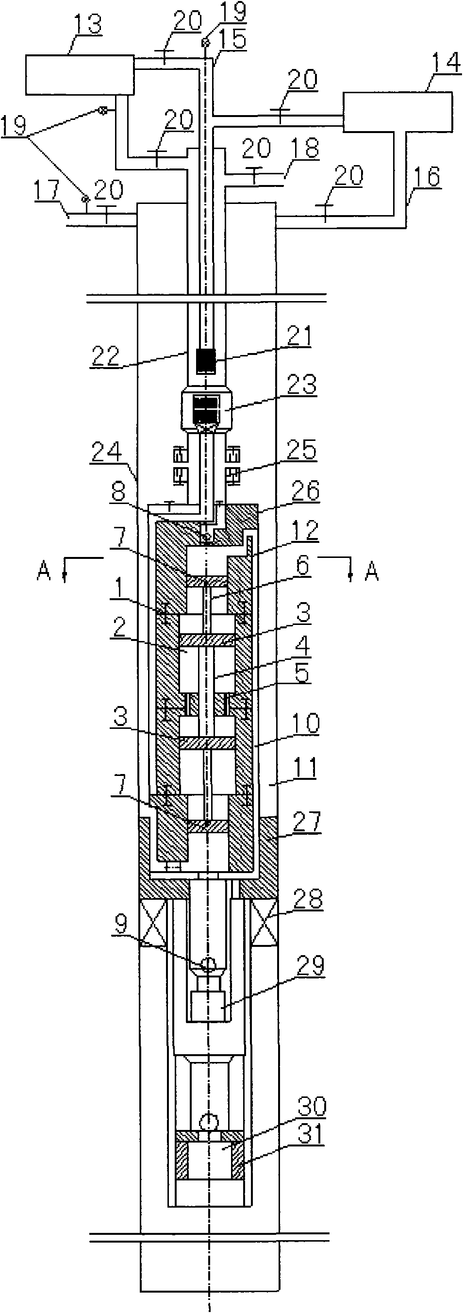
pipe, casing is sleeved on the outside of oil pipe, and on the oil pipe A sealing seat, a pressurized oil production pump, a pump holder, a packer, a filter pipe valve and a filter pipe are arranged in sequence, a switchable sliding sleeve is arranged on the oil pipe under the sealing seat, and a gas injection pipe is arranged inside the oil pipe. The end of the gas injection pipe is provided with a stop valve plug, the gas injection pipe is connected to the sealing seat through the stop valve plug, the gas injection pump is connected with the intake pipe of the booster oil production pump through the valve, pipeline and gas injection pipe, and the waste gas recovery tank is connected through the valve and pipeline Connected with the annular space between the tubing and the casing, the booster pump includes a cylinder liner, a cylinder cavity, a piston, a piston connecting rod, a connecting rod seal assembly, a plunger, a plunger connecting rod, a fixed valve, and an oil inlet valve And the oil outlet valve, the oil outlet valve is set on the top of the booster oil production pump, and the fixed valve and the oil inlet valve are set at the bottom of the booster oil recovery pump. The inner cavity is provided with a plunger and a piston, the plunger is connected to the piston through the plunger connecting rod, the piston is connected to the piston through the piston connecting rod, and the inner cavity of the cylinder is connected to the intake pipeline and the exhaust pipeline through the intake valve and the exhaust valve. The inner chamber of the plunger is connected with the oil inlet pipeline and the oil pipe through the fixed valve, the oil inlet valve and the oil outlet valve. The pipe valve and the filter pipe are connected to the oil pipe, put the oil pipe into the casing of the wellbore, and then clamp the pump clamp; fill the oil pipe with liquid, open the valve next to the pressure relief port, and close the other valves at the same time, and pump the pump to the oil pipe and the casing. Inject liquid into the annular space between them for pressure test, record the maximum value of the pressure gauge, relieve the pressure on the casing, then open the valve next to the liquid outlet to relieve the pressure on the oil pipe, close the valve below the air injection pump, and connect a stop valve from the oil pipe The gas injection pipe of the plug is lowered into the well; every time it descends 600-700m, open the valve below the gas injection pump, inject gas into the annular space between the oil pipe and the gas injection pipe, discharge the liquid from the gas injection pipe, and pass through the valve on the left of the waste gas recovery tank Enter the exhaust gas recovery tank, when the stop valve plug is lowered to a position one meter away from the sealing seat, and the fluid discharged from the exhaust gas recovery tank is all gas, insert the stop valve plug into the sealing seat, and open the channel of the sealing seat after pressurization ;Close the valve on the left and below the exhaust gas recovery tank, open the valve below the gas injection pump, inject gas into the annular space between the oil pipe and the gas injection pipe, pressurize and test the sealing effect between the stop valve plug and the sealing seat; install the wellhead equipment, open the valve on the right side of the gas injection pump to inject gas into the gas injection pipe, open the valves next to the pressure relief port and the liquid outlet, take samples and analyze from the pressure relief port and liquid outlet respectively, record the value of the pressure gauge, and adjust the pumped gas pressure and Gas volume; close the valve next to the pressure relief port, open the valve on the right side of the gas injection pump and under the waste gas recovery tank, let the circulating gas be pumped into the gas injection pipe again, open the valve next to the pressure relief port and under the waste gas recovery tank, and sample Analyze gas humidity and oil content, calculate production

Method used


Image

  • Deep well gas injection supercharging mechanical oil production method and device
  • Deep well gas injection supercharging mechanical oil production method and device

Examples


Embodiment Construction

[0006] Combine below figure 1 and figure 2 The deep well gas injection supercharging mechanical oil recovery method and device of the present invention are further described. The method adopts the deep well gas injection supercharging mechanical oil recovery device. The oil pump 26, the pump bracket 27, the packer 28, the filter pipe valve 30 and the filter pipe 31, the casing 24 is sleeved on the outside of the oil pipe 22, and the oil pipe 22 is provided with a sealing seat 23, a pressurized oil recovery pump 26, Pump frame 27, packer 28, filter tube valve 30 and filter tube 31, a switchable sliding sleeve 25 is arranged on the oil pipe 22 below the sealing seat 23, an air injection pipe 15 is arranged inside the oil pipe 22, and an air injection pipe The end of 15 is provided with a stop valve plug 21, the gas injection pipe 15 is connected to the sealing seat 23 through the stop valve plug 21, and the gas injection pump 13 communicates with the intake pipeline 1 of the b...


PUM


Abstract

The invention provides a deep well gas injection supercharging mechanical oil extraction method and device, which belongs to the method or equipment technique field for extracting oil from well, and solves insufficient lifting ability problem of prior mechanical oil extraction method and device, the method uses a deep well gas injection supercharging oil extraction device, and specifically includes the steps of: connecting a sealing base, a supercharging oil extraction pump, a pump fastening rack, a packer, a filter tube valve and a filter tube to the oil conduit, placing the oil conduit into the well bore casing tube, and fastening the pump-fastening rack; injecting liquid into the annular spacing between the oil conduit and casing tube, testing pressure and relieving pressure; injecting gas into the annular spacing between the oil conduit and the air injection tube, discharging liquid from the gas injection tube; installing wellhead equipment, adjusting pressure and air flow of pumped air, sampling humidity and oil content of analysis gas, calculating quantity of production. The method and device provided by the invention use gas as power medium for periodic duty recyclablely, which causes the lifting pressure up to 2-5 times of gas pressure, and the process flow is simple and is suitable for oil extraction of deep well and mechanical oil extraction of thick oil well.

Description

1. Technical field [0001] The invention belongs to the technical field of methods or equipment for extracting oil from wells, and in particular relates to a deep well gas injection mechanical oil extraction method and device. 2. Background technology [0002] At present, human beings use the raw energy of deep oil layers to exploit deep oil. However, the oil extracted by relying on the original energy of the oil layer only accounts for 3% of the recoverable oil layer, and most of the deep oil relies on mechanical extraction. Due to the limitations of the lifting capacity of the existing mechanical oil production equipment and the production technical scheme, the oil with a buried depth below 4500 meters and a hydrostatic oil level below 4000 meters cannot be normally extracted, or even cannot be extracted. In recent years, people have designed new mining equipment such as hydraulic plunger pumps and gas injection pumps, trying to use hydraulic plunger pumps or gas injection...

Claims


Application Information

Patent Timeline
Patent Type & Authority Applications(China)
IPC IPC(8): E21B43/18
Inventor 甘振维赵海洋林涛邓洪军张志宏刘榧张建军柏森黄云胡雅洁杨映达杨祖国
Owner CHINA PETROLEUM & CHEM CORP
Why Eureka
Try Eureka