Intelligent opto-electrical direct reader

A photoelectric direct reading and photoelectric sensor technology, applied in the field of instruments and measuring instruments, can solve the problems of unintuitive production process, increased cost, increased volume, etc., and achieve the effect of improving anti-light interference performance and stabilizing communication

Active Publication Date: 2009-11-04
深圳市骏普科技开发有限公司
View PDF6 Cites 17 Cited by
  • Summary
  • Abstract
  • Description
  • Claims
  • Application Information

AI Technical Summary

Problems solved by technology

With the development of technology, photoelectric direct reading technology has developed rapidly in the past two years, but the existing intelligent photoelectric direct reading devices used for measuring instruments and meters have obvious shortcomings: 1. It is easy to be interfered by external light , when the external light is too strong, measurement errors are prone to occur. In order to reduce the impact of external light on the photoelectric direct reading device, many manufacturers use far-infrared infrared photoelectric pair tubes, but the external light in the environment where the photoelectric direct reading device is located is a When the external light reaches a certain intensity, even if the far-infrared photoelectric tube is used, it cannot effectively solve the problem of light interference; 2. Most products use the switching value measurement principle, although a few use analog-to-digital conversion (ADC) technology, but "0" and "1" logical boundary thresholds adopt fixed values, which cannot effectively resist the problem of external interference; 3. If the internal RC oscillator of the single-chip microcomputer is used, the instability of the RC oscillator may easily lead to unstable communication. Resulting in abnormal data transmission,

Method used


Image

  • Intelligent opto-electrical direct reader
  • Intelligent opto-electrical direct reader

Examples


Embodiment Construction

[0015] Below in conjunction with accompanying drawing, the present invention will be further described:

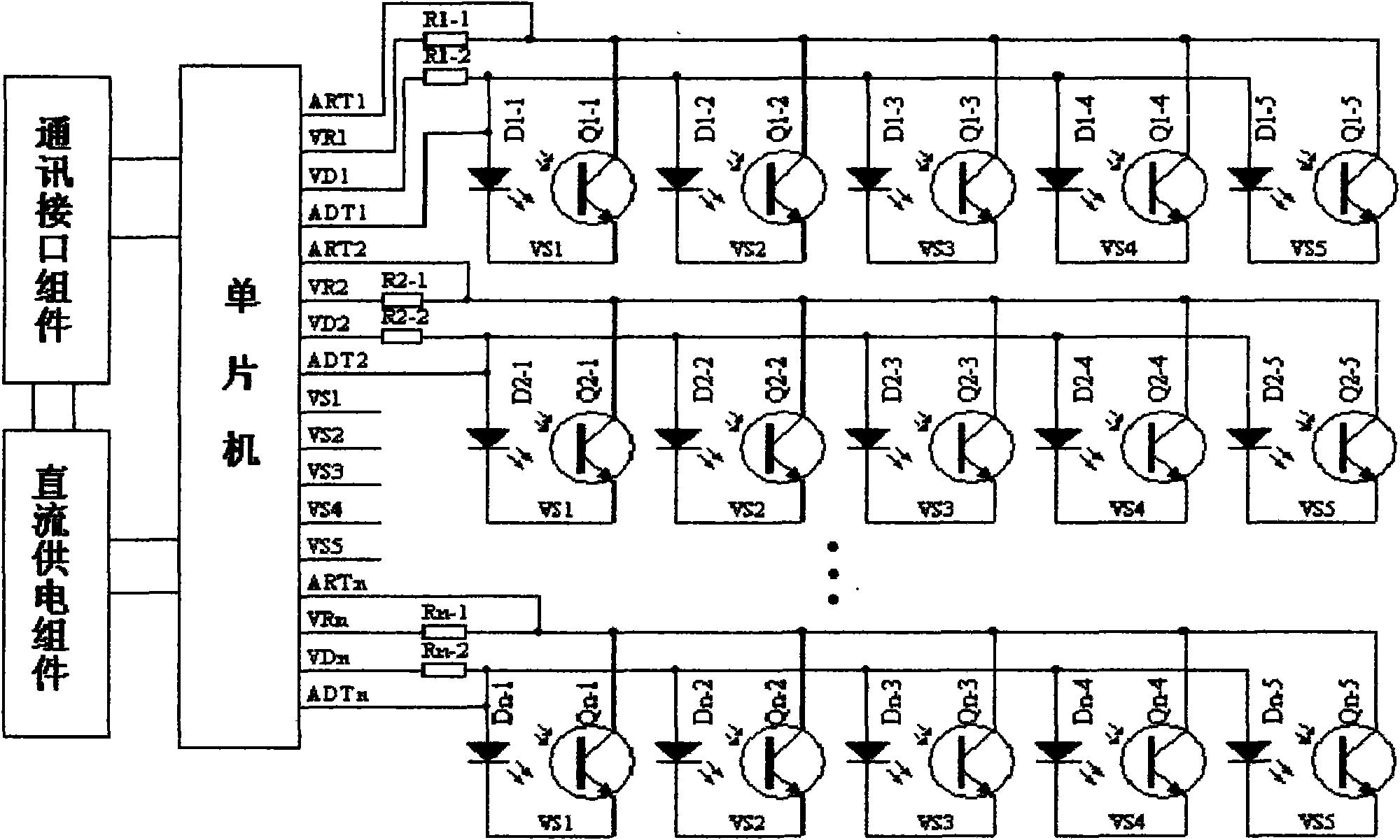
[0016] Such as figure 1 As shown: the intelligent photoelectric direct reader provided by this embodiment includes: a single-chip microcomputer, a communication interface assembly, a DC power supply assembly, and a plurality of groups of photoelectric sensors composed of multiple pairs of photosensitive receiving tubes and light emitting tubes. coder components, the figure 1 Among them, a photoelectric sensor composed of 5 pairs of photosensitive receiving tubes and a pair of light emitting tubes is used, and a photoelectric sensor decoder is composed of n groups of photoelectric sensors. The photoelectric sensor decoder provides a detailed electrical principle connection diagram. figure 1 Among them, Dn-m, and Qn-m (m represents the marked number of 1-5) form a pair of light emitting tubes, photosensitive receiving tubes, Dn-1, and Qn-1 to Dn-5, and Qn-5 A total of 5 pa...


PUM


Abstract

The invention discloses an intelligent photo-electrical direct reader, comprising a single chip, a communication interface component, a DC supply component, and a plurality of photo-electrical sensingdecoder components, which are composed of plural pairs of photo diodes and light-emitting tubes, plural photo-electrical sensor components; an RC vibrator in the single chip is used as a system clock, the method of modifying an OSCCAL register data which is used for marking the RC vibrator is used for marking the RC vibrator, the photo diode and the light-emitting tube of each photo-electrical sensor component are supplied by the port of the single chip independently, the public end of the photo-electrical pair tube at the position corresponding to the photo-electrical sensing decoder components is controlled by the port of the same single chip, the measurement data (ADC) is processed by concrete quantized method, the external light of the photoelectric sensor as well as the electric property state of the actual measured sensing signal and the pair tube of the photoelectric sensor are scanned and measured, '0' and '1' logic level comparison threshold values can be adjusted dynamically, when the state of the photoelectric sensor is wrong, the code redundancy compensation algorithm can be initiated to correct the data, after the data information is processed by validation algorithm,different addresses are stored as back-up; the direct reader of the invention has the characteristics of high disturbance resisting capacity and low cost.

Description

Technical field: [0001] The invention relates to an intelligent photoelectric sensor, which is suitable for measuring instruments, instruments and equipment that need to output electrical signal codes for the readings displayed by mechanical counters, especially digital transmission direct-reading water meters, gas meters, electric meters, etc. Measuring instruments and meters that display numbers corresponding to the rotation position of the wheel and output electrical signal codes. Background technique: [0002] At present, there is a device that reads the reading information of a meter by adding a photoelectric sensor component to the automatic remote meter reading technology, that is, a photoelectric direct reading sensor device, referred to as a photoelectric direct reading device. The device transforms the counter character wheel of the original mechanical counter device, and uses photoelectric sensor components to convert the ten numbers "0"-"9" on the counter charact...

Claims


Application Information

Patent Timeline
IPC IPC(8): G01D5/347G01J1/44
Inventor 吴明星
Owner 深圳市骏普科技开发有限公司
Why Eureka
Try Eureka