Nano-material surface-catalyzed luminescent micro-sensor

A micro-sensor and nanomaterial technology, applied in chemiluminescence/bioluminescence, analysis by chemical reaction of materials, etc., can solve the problem of poor stability and reproducibility of luminescence signal, affecting the accuracy of quantitative analysis, and broadening of luminescence signal curve and other problems, to achieve the effect of improved resolution and detection sensitivity, rapid response time, and shortened response time.

Inactive Publication Date: 2009-11-04
刘名扬
View PDF0 Cites 5 Cited by
  • Summary
  • Abstract
  • Description
  • Claims
  • Application Information

AI Technical Summary

Problems solved by technology

Due to the long time for the sample to flow through the surface of the nanocatalytic material through the carrier gas and the large dead volume, it is easy to cause problems such as long luminescence response time and broadening of the luminescence signal curve, resulting in poor stability and reproducibility of the luminescence signal and low measurement accuracy. Affect the accuracy of quantitative analysis

Method used


Image

  • Nano-material surface-catalyzed luminescent micro-sensor
  • Nano-material surface-catalyzed luminescent micro-sensor

Examples


Embodiment 1

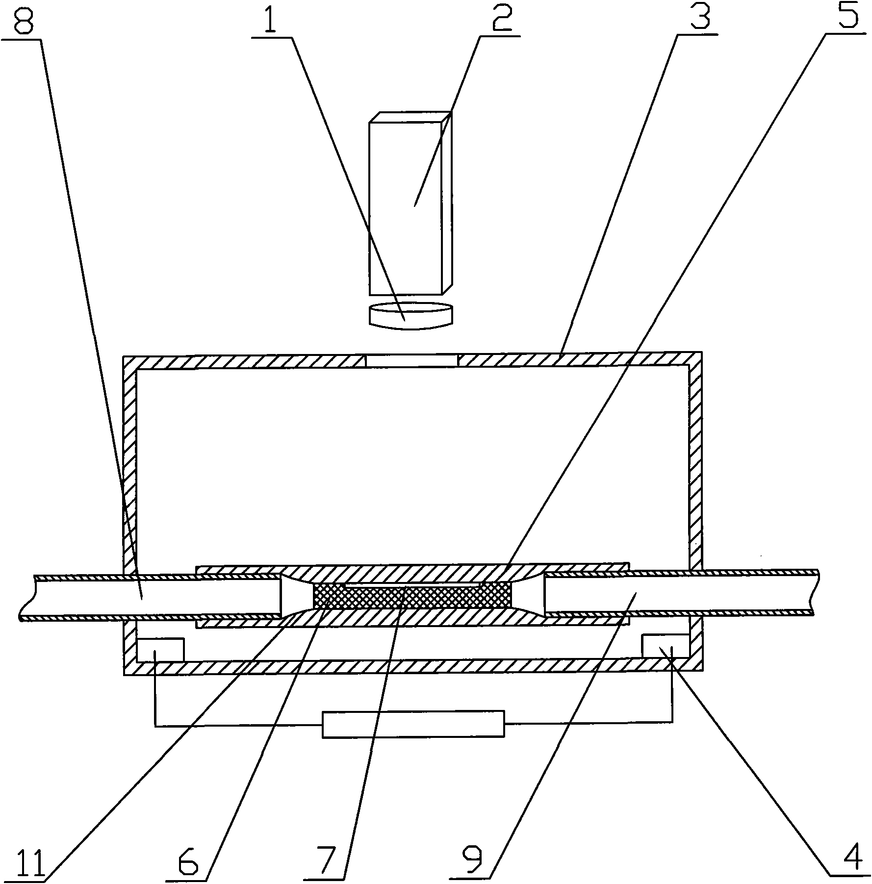
[0015] Such as figure 1 As shown: the material and the fixing method are the same as the optical filter or grating 1 and the photoelectric signal conversion device 2 of the prior art. The difference from the prior art is that a housing 3 is provided, and a heating element 4 is built in the housing 3 And the quartz capillary 5, the heating element 4 and the quartz capillary can be any one of the prior art, and the heating element 4 can be connected with the temperature control circuit, so that the temperature factors affecting the catalytic luminescence can be accurately controlled. The inner wall of the quartz capillary 5 is coated with a nanomaterial 6, but a part of the blank must be left, that is, the light-transmitting surface 7, such as the nanomaterial 6 is only coated on the lower side of the inner wall of the quartz capillary 5 or a blank is left on the upper side. . The light-transmitting surface 7 is arranged opposite to the optical filter or the grating 1 , and the...

Embodiment 2

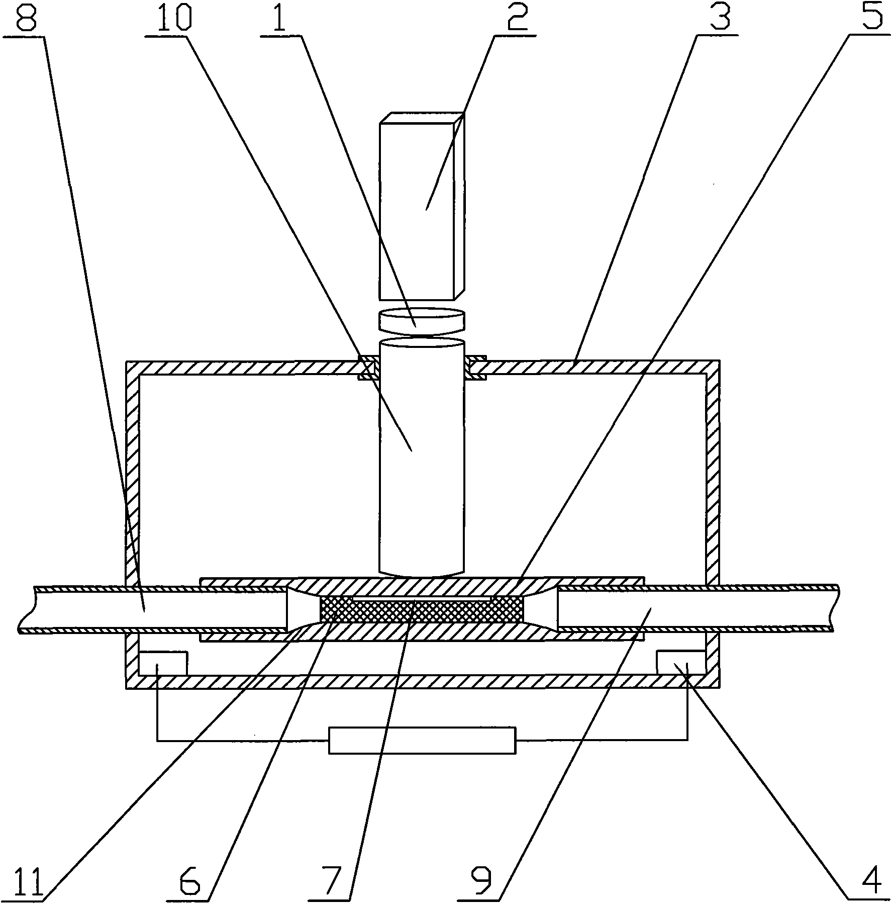
[0017] Such as figure 2 Shown:

[0018] The basic structure is the same as that of Embodiment 1. The difference from Embodiment 1 is that in order to avoid the loss of optical signals and the interference of stray light, a light-conducting element 10 is placed between the light-transmitting surface 7 and the filter or grating 1 . The diameter of the middle part of the quartz capillary 5 is smaller than that of both ends, and the diameter of the middle part is 0.1-0.75 mm. There is a smooth transition surface 11 between the middle part and both ends, and the nanomaterial 6 is coated on the middle part. For the convenience of the connection and disassembly of the quartz capillary 5 with the sample tube 8 and the vent tube 9, the sample tube 8 and the vent tube 9 are preferably capillaries, and the polyimide coating on the outside of the capillary can ensure tightness. Inserted at both ends of the quartz capillary 5, the light conducting element 10 is an optical fiber.

[0019...


PUM

PropertyMeasurementUnit
diameteraaaaaaaaaa

Abstract

The invention discloses a nano-material surface-catalyzed luminescent micro-sensor, which is simple in structure, capable of shortening detection time, good in stability and reproducibility and high in detection efficiency and precision. The micro-sensor has an optical filter or grating (1) and a photoelectric-signal conversion device (2) and is provided with a shell (3), wherein a heating element (4) and a quartz capillary tube (5) are arranged inside the shell (3); the inner wall of the quartz capillary tube (5) is coated with nano-material (6) and is provided with a light transmission surface (7); the light transmission surface (7) is arranged opposite to the optical filter or grating (1); and two ends of the quartz capillary tube (5) are connected with a sample inlet tube (8) and an escape tube (9) respectively.

Description

Technical field: [0001] The invention relates to a nanomaterial surface catalytic luminescence sensor, in particular to a nanomaterial surface catalytic luminescence microsensor with simple structure, shortened detection time, good stability and reproducibility, high detection efficiency and precision. Background technique: [0002] Nanomaterial surface catalytic luminescence sensors are widely used, such as quantitative evaluation of nanomaterial catalytic activity, quantitative detection of ethanol, methanol and petrochemical products, detection of hormone drug residues in food, and selection of capillary gas chromatography type detector, etc. The structure of the existing nano-material surface catalytic luminescence sensor is to place the electrothermal ceramic rod with a diameter of 4-7 mm coated with nano-materials in a quartz tube with a diameter of 12-20 mm and a length of 100-150 mm, and set it diagonally on the quartz tube. There are sample inlets and vents, and ou...

Claims


Application Information

Patent Timeline
Patent Type & Authority Applications(China)
IPC IPC(8): G01N21/76
Inventor 刘名扬赵景红刘盛莉陈梦阳盛向军周硼邹明强杨连春
Owner 刘名扬
Why Eureka
Try Eureka