


Quick Research
Generate reliable direction feasibility study reports for your R&D in just a few steps.

Technical Q&A
Discover and master advanced knowledge NOW. Basics, ideas, possibilities, all at once.

Find Solutions
As an expert in R&D theories, this can generate solutions to your technical problems instantly.

Evaluate Feasibility
Analyze your overall solution with one click, know your potential R&D risks in advance.

Monitor Landscape
Get weekly tech updates, stay abreast of the latest tech innovations and key insights.
2.12 micron mode-locked laser
A mode-locked laser and laser gain technology, applied in lasers, laser parts, phonon exciters, etc., can solve the problems of high technical requirements, low laser conversion efficiency, and high cost, and achieve small size, low cost, and stability. high sex effect
- Summary
- Abstract
- Description
- Claims
- Application Information
AI Technical Summary
Problems solved by technology
Method used
Image

Examples
Embodiment 1
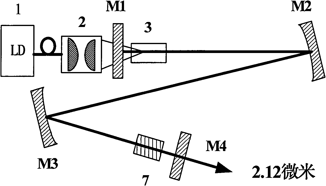
[0024] Such as figure 1 Make a 2.12 micron continuous mode-locked laser, the laser gain crystal 3 is Nd:YVO 4 , the parameters of each cavity mirror are: the input plane mirror M1 is a plane mirror with high reflection to 1.06 micron laser; the plano-concave mirror M2 is a plano-concave mirror with a radius of curvature of 500 mm; the plano-concave mirror M3 is a plano-concave mirror with a radius of curvature of 300 mm; Chromatic mirror M4 is a flat mirror with high reflection to 1.06 micron laser and 3% transmittance to 2.12 micron laser. The total length of the laser cavity is about 1.7 meters, and the distance between the input plane mirror M1 and the plano-concave mirror M2 is about 540 mm, the distance between the plano-concave mirror M2 and the plano-concave mirror M3 is about 950 mm, and the distance between the plano-concave mirror M3 and the dichroic mirror M4 is about 190 mm . Potential Phase Matched Crystal LiNbO 3 The length is 20 mm, and the phase-matched crys...
Embodiment 2
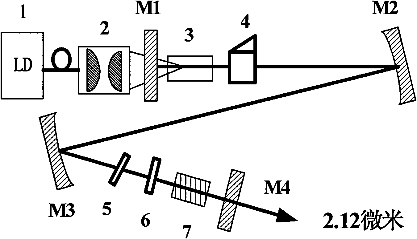
[0026] Such as figure 2 Make a 2.12 micron Q-switched mode-locked laser, including diode pump source 1, coupling system 2, input plane mirror M1, laser gain crystal 3, optical switch 4, plano-concave mirrors M2, M3, phase compensation sheet 5, group velocity loss Equipped with compensation sheet 6, quasi-phase matching crystal and crystal temperature control furnace 7 and dichroic mirror M4, the light source generated by diode pump source 1 passes through coupling system 2 and input plane mirror M1, pumps laser gain crystal 3, and is controlled by optical switch 4 Obtain Q-switched mode-locked pulses, plano-concave mirrors M2 and M3 compress the oscillating beam, phase compensation film 5 eliminates the influence of phase mismatch on pulse width and shape, and group velocity mismatch compensation film 6 eliminates the influence of group velocity dispersion on pulse width and shape The quasi-phase matching crystal and the crystal heating furnace 7 and the dichroic mirror M4 wo...
PUM
 Abstract
Description
Claims
Application Information
 - R&D Engineer
- R&D Manager
- IP Professional
- Industry Leading Data Capabilities
- Powerful AI technology
- Patent DNA Extraction
Browse by: Latest US Patents, China's latest patents, Technical Efficacy Thesaurus, Application Domain, Technology Topic, Popular Technical Reports.
© 2024 PatSnap. All rights reserved.Legal|Privacy policy|Modern Slavery Act Transparency Statement|Sitemap|About US| Contact US: help@patsnap.com