
Image ratio constant flow source circuit driving multipath light emitting diode

A technology of light-emitting diodes and constant current sources, applied in the field of electronics, can solve problems such as low-cost constant-current source circuits, and achieve the effects of stable luminous intensity, low cost, and convenient use

Inactive Publication Date: 2009-11-04
JILIN UNIV
View PDF0 Cites 23 Cited by
  • Summary
  • Abstract
  • Description
  • Claims
  • Application Information

AI Technical Summary

Problems solved by technology

At present, there is no constant current source circuit that can drive multiple light-emitting diodes in current mode at the same time, the driving current of each channel can be adjusted independently, the structure is relatively simple, and the cost is relatively cheap.

Method used


Image

  • Image ratio constant flow source circuit driving multipath light emitting diode
  • Image ratio constant flow source circuit driving multipath light emitting diode

Examples


Embodiment 1

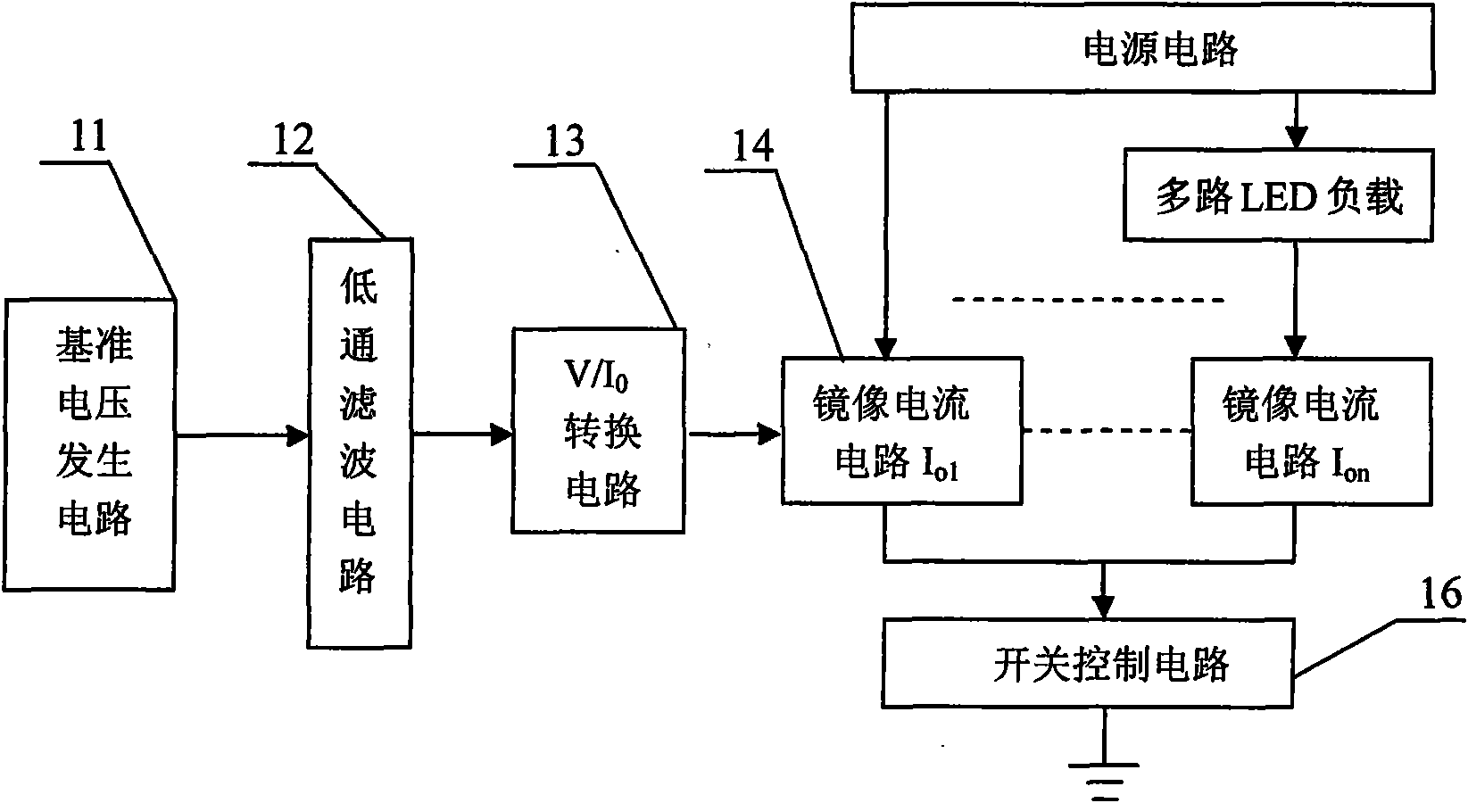
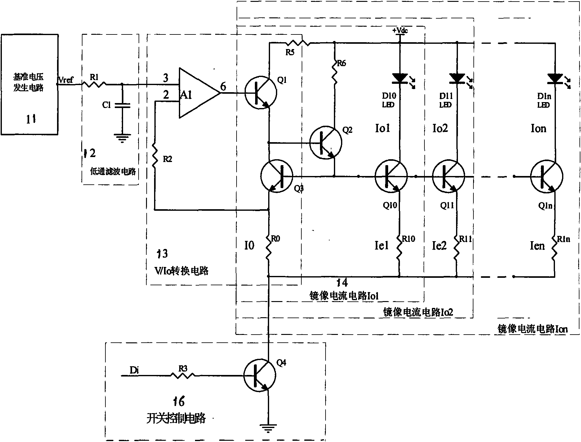
[0020] see figure 1 and figure 2 , the present invention is a mirror image proportional constant current source circuit for driving multiple light emitting diodes, which includes a reference voltage generation circuit 11, a low-pass filter circuit 12, a V / I 0 Conversion circuit 13, multi-channel mirror image proportional constant current source circuit 14 and switch control circuit 16; the voltage signal Vref generated by the reference voltage generating circuit 11 is input to the V / I through the low-pass filter circuit 12 formed by the resistor R1 and the capacitor C1 0 The noninverting input terminal pin 3 of the operational amplifier A1 of the conversion circuit 13; the inverting input terminal pin 2 of the operational amplifier A1 is connected to one end of the sampling resistor R0 in the reference input constant current source channel through a balance resistor R2, and the sampling resistor The other end of R0 is connected to the collector of the fourth transistor Q4 in t...


PUM


Abstract

The invention provides an image ratio constant flow source circuit driving a multipath light emitting diode, belonging to the electronic technical field. The circuit structure comprises a pedestal generation circuit (11), a low-pass filter circuit (12), a V / I0 conversion circuit (13), a multipath image ratio constant flow source circuit (14) and a switch control circuit (16), wherein the image ratio constant flow source circuit (14) comprises transistors (Q10, Q11, ... Q1n), Light Emitting Diode loads (D10, D11, ... D1n), ratio resistors (R10, R11, ... R1n) and a sampling resistor (R0); the switch control circuit (16) comprises a third resistor (R3) and a fourth transistor (Q4), and completes control action by a digital signal (Di). The circuit of the invention leads illumination intensity of the multipath light emitting diode to be stable, can obtain continuous spectrum or modulated spectrum, has convenient use, low cost and electricity conservation, and is convenient for portable instrument use.

Description

technical field [0001] The invention belongs to the field of electronic technology, in particular to a mirror image ratio constant current source circuit for driving multiple light emitting diodes. Background technique [0002] As we all know, the halogen tungsten lamp is the most widely used light source on the spectrometer. Its main advantage is that its radiated spectrum can cover the entire visible to near-infrared region, and it is a continuous spectrum, which realizes continuous Scanning provides the possibility to obtain relatively high resolution. However, tungsten-halogen lamps also have many disadvantages as light sources, such as high power consumption, high heat generation, short service life, effective heat insulation and heat dissipation devices between optical components and tungsten-halogen lamps, etc., therefore, it is not suitable as a Light source use for portable instruments. [0003] Light-emitting diode (LED) is a new type of semiconductor light-emitt...

Claims


Application Information

Patent Timeline
IPC IPC(8): H05B37/02F21V23/00H02M3/04F21Y101/02F21Y115/10
Inventor 曹彦波王兴华于永宋大千费强
Owner JILIN UNIV
Learn More