Printed circuit board and method for its production

A printed circuit, printed circuit board technology, applied in the direction of printed circuit manufacturing, printed circuit, printed circuit, etc., can solve problems such as total module failure

Active Publication Date: 2013-09-04
AGIE CHARMILLES +1
View PDF1 Cites 0 Cited by
  • Summary
  • Abstract
  • Description
  • Claims
  • Application Information

AI Technical Summary

Problems solved by technology

Delamination and bubble formation of the individual layers of the printed circuit board can be caused in the event of a fault and thus lead to a total failure of the entire module

Method used


Image

  • Printed circuit board and method for its production
  • Printed circuit board and method for its production
  • Printed circuit board and method for its production

Examples


Embodiment Construction

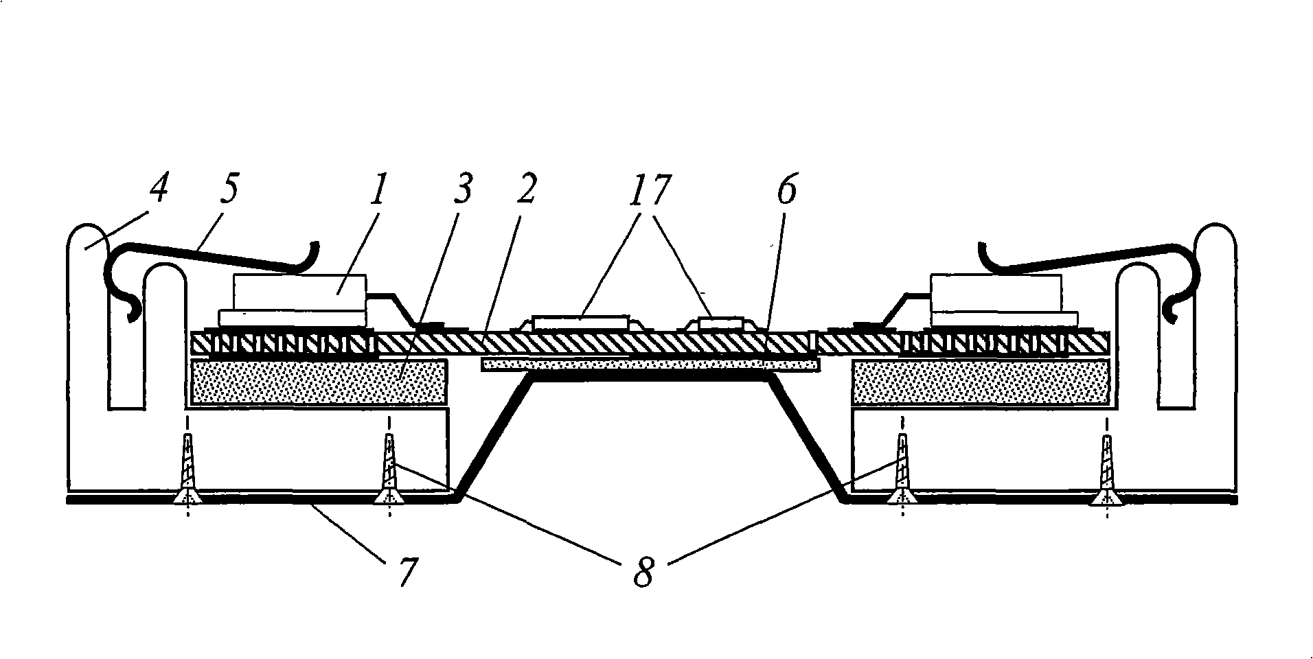
[0044] figure 1 A first embodiment of a printed circuit unit according to the invention (hereinafter also referred to as a power module or simply a module) is shown, which can be produced, for example, at least in part from commercially available components. in detail figure 1 Before the embodiments of the present invention, the embodiments of the present invention and their advantages will be generally described.

[0045] Some embodiments of a printed circuit unit according to the invention comprise a printed circuit board (which in some embodiments is discontinuous) and one or more cooling bodies (hereinafter also referred to as cooling (body) profiles). Solder surface-mountable components on the printed circuit board, the so-called SMD (Surface Mounted Device) components. The characteristic of SMD technology is that the components can be soldered directly on the printed circuit board. In some embodiments, in particular SMD components generating high thermal power are loc...


PUM


Abstract

The method involves arranging thermally loaded surface-mountable conductive elements (1) e.g. surface mount device, in heat conducting regions on a printed circuit board (2). A thermally conductive and electrically isolative layer (3) is arranged between the conductive elements and cooling bodies (4) in a region of through-contacts. The conductive elements with an elastic clip (5) are pressed against the cooling bodies above the circuit board such that heat produced by the conductive elements is dissipated to the cooling bodies by the through-contacts. The thermally conductive and electrically isolative layer is made of ceramic. An independent claim is also included for a printed circuit board unit comprising a printed circuit board.

Description

technical field [0001] The invention relates to a printed circuit unit for eg power electronics applications and a method for its production. Background technique Background of the invention [0002] Tasks that were previously mainly solved by mechanical or electromechanical means are now increasingly frequently being solved, for example, by power electronic solutions. Here, rising labor and material costs as well as the size and weight of electronic components are major obstacles to transformative solutions. The cost-intensive part is mainly the manual assembly of components that generate high thermal power, such as power semiconductors, and their mounting on cooling devices that dissipate the generated thermal power as heat. The reliability of components currently depends especially on the quality of these manual processes. Quality control thus becomes increasingly expensive. [0003] The manufacture, inspection, operation and maintenance of such electronic assemblies...

Claims


Application Information

Patent Timeline
Patent Type & Authority Patents(China)
IPC IPC(8): H05K1/02H05K7/20H01L23/40H01L23/46
CPCH01L2924/0002H05K3/0061H01L23/473H05K7/20472H01L23/4093H05K2201/10393H05K7/2089H05K7/20409H05K7/2049H05K1/141H05K1/0206H05K2201/10166
Inventor 恩斯特·布勒雷托·克纳克里诺·达马里奥罗萨里奥·隆巴多
Owner AGIE CHARMILLES
Why Eureka
Try Eureka