High-power LED lamp based on heat pipe for thermal conductivity

A LED lamp, high-power technology, applied in the direction of semiconductor devices, lighting and heating equipment, components of lighting devices, etc., can solve the problems of large thermal resistance, small radiator contact surface, complex circuit design, etc., to achieve enhanced heat dissipation effect , expand the scope of use, improve the effect of cooling efficiency

Inactive Publication Date: 2009-11-11
ZHEJIANG MINGXIN SEMICON TECH
0 Cites 8 Cited by

AI-Extracted Technical Summary

Problems solved by technology

One is to use a low-power LED array as the illuminant, but low-power LEDs have large light attenuation, complex circuit design, high installation costs, and difficulties in light distribution control
The other uses high-power LED chips to be integrated and packaged in a metal base, and an optical cup is arranged on the base. This package structure has high light efficiency and is easy to control the luminous angle. However, the existing problem is that the problem of heat dissipation has not been resolved solve
The bottom plane of the existing high-power LED base is conne...

Method used

As shown in Figure 3, heat pipe 43 is the round tube with cavity of tool to store liquid; Radiator 41 comprises the metal cooling fin 42 that plural sheet vertically arranges in parallel, and metal cooling fin 42 has plural number for The air flow hole 45 for air convection and a plurality of connecting holes 44 arranged side by side for passing through the heat pipe 43 . The air circulation holes 45 are rectangular holes arranged symmetrically up and down and with flanges on the outer periphery; the connecting holes 44 are cylindrical and have flanges on the outer periphery; the outer periphery of the cooling fins 42 is covered with a heat dissipation and cooling layer. The inner groove 47 on the chip base 46 is a through groove arranged in parallel; the heat pipe 43 and the connection hole 44 are connected and fixed by metal welding, and the greater the power of the LED lamp, the more the number of the inner groove 47 to accommodate ...

Abstract

The invention discloses a high-power LED lamp based on a heat pipe for thermal conductivity and relates to an LED lamp. The prior high-power LED lamp has unsatisfactory heat transference and poor heat dissipation effect. The high-power LED lamp comprises an LED chip, a chip base, a heat dissipation device which is connected with the chip base and a light distribution device which is arranged on the chip base. The high-power LED lamp is characterized in that the heat dissipation device comprises a heat radiator and a plurality of heat pipes which connect the heat radiator with the chip base; and a plurality of inner grooves which are matched with the heat pipes are correspondingly formed on the chip base for containing the heat pipes, and a metal welding layer is arranged between the inner grooves and the heat pipes for connecting the chip base which is covered by the chip with the heat radiation device so as to form an integrated light source. The technical method has good heat conduction effect, rapid heat dissipation and reliable connection.

Application Domain

Technology Topic

Image

  • High-power LED lamp based on heat pipe for thermal conductivity
  • High-power LED lamp based on heat pipe for thermal conductivity
  • High-power LED lamp based on heat pipe for thermal conductivity

Examples

  • Experimental program(1)

Example Embodiment

[0026] The technical solution of the present invention will be further described in detail below in conjunction with the accompanying drawings.
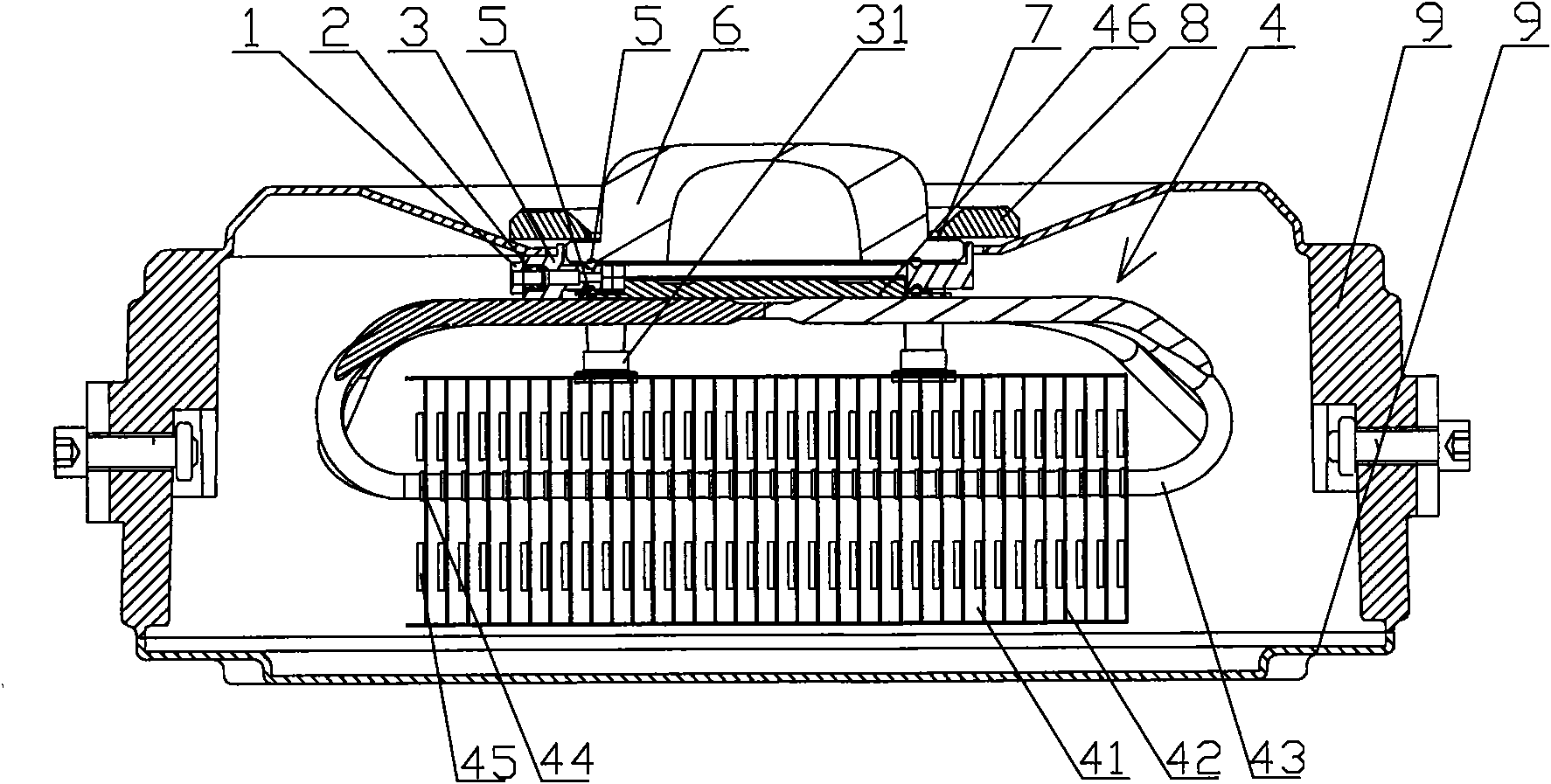
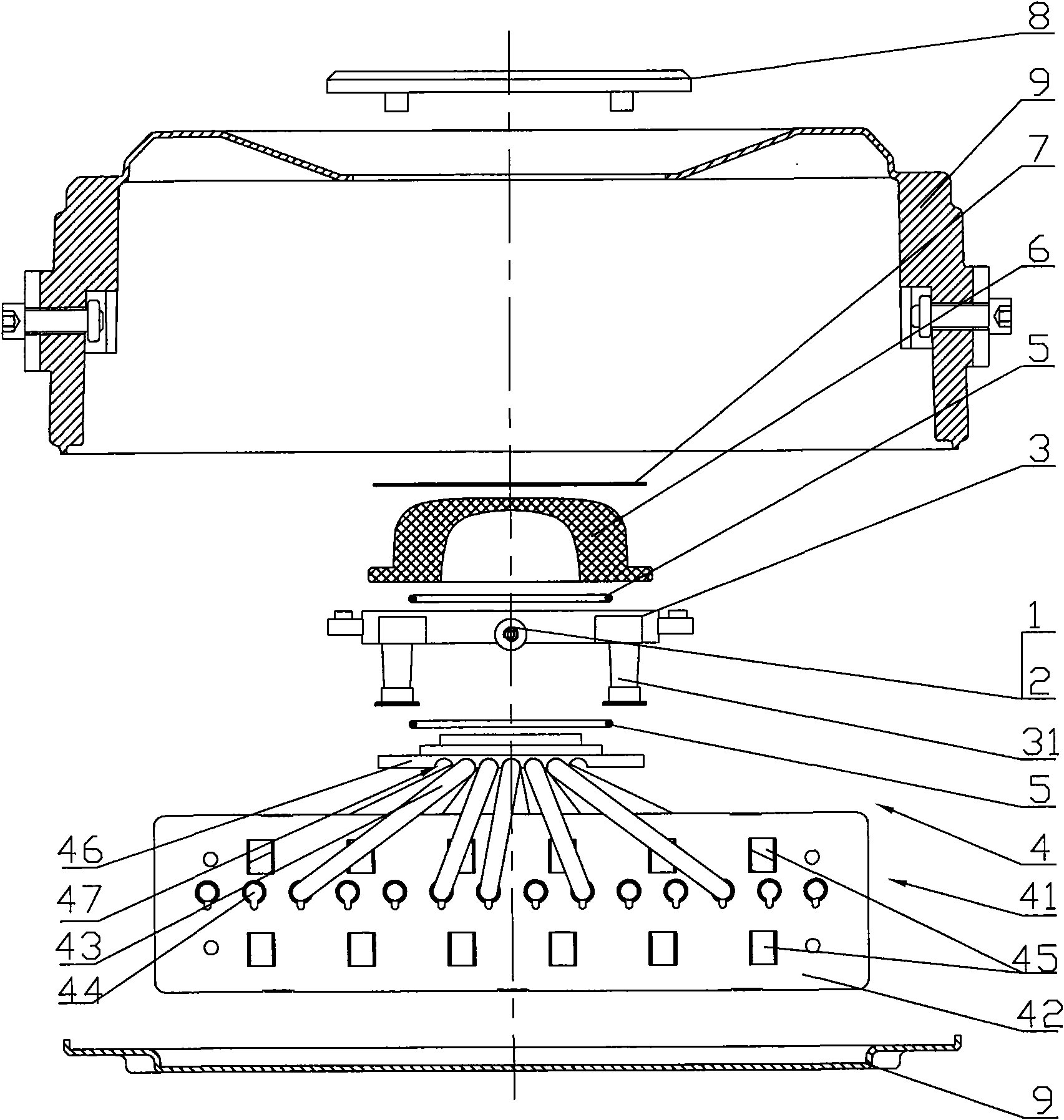
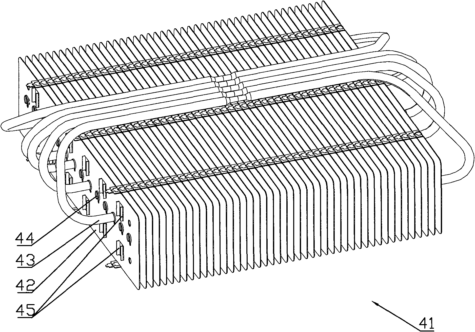
[0027] like figure 1 , 2 Shown, the present invention comprises LED chip, chip base 46, the cooling device that links to each other with chip base 46 and the light distribution device that is located on the chip base 46; The heat pipe 43 of the chip base 46; the chip base 46 is correspondingly provided with a plurality of inner grooves 47 matched with the heat pipe 43 for accommodating the heat pipe 43, and the inner groove 47 can be semicircular, "V" Shaped, "U" shaped or polygonal groove, in this embodiment a semicircular inner groove 47 is used, so that the circular heat pipe 43 can be closely attached to the wall of the inner groove 47, and lead-free tin A layer of flux welds the two together. The chip is covered on the chip base 46 by thermally conductive silver paste.
[0028]The light distribution device comprises a light distribution lens 6 positioned above the chip, a cover for fixing the lens 6 and a lens base 3; the lens base 3 is fixed on the chip base 46 by screws; the connection between the lens base 3 and the lens 6 An annular sealing ring 5 is provided between the lens base 3 and the chip base 46 . A light transmission hole matched with the LED chip is provided in the middle of the lens base 3 , and a plurality of anti-vibration support columns 31 that can be in contact with the heat sink 41 are provided on the outer periphery thereof. The side of the lens base 3 is provided with an outlet hole for the power supply line of the chip light source, and an outlet hole sealing ring 52 is placed in the outlet hole. The outlet hole nut 1 compresses and seals the outlet hole sealing ring 52 . The outer periphery of the integrated light source 4 formed by the chip-covered chip base 46 and the cooling device is provided with a fixing device. The fixing device includes a lamp housing 9 with a light outlet. The light outlet of the lamp housing 9 is located on the lens gland 8 and the lens. Between the bases 3; the lens gland 8 is threaded through the screw that is screwed on the lens base 3, so that the lens gland 8 and the lens base 3 clamp the light outlet of the lamp housing 9 to integrate the light source, seal and accessories. The optical lens 6 is fixed on the lamp housing 9 , and the threaded holes of the lens base 3 are located on the four anti-vibration support columns 31 . The assembly process of the light distribution device is as follows: the lens base 3 is fixed on the upper part of the substrate of the integrated light source 4 with bolts, and the sealing ring 5 is placed therebetween; the light distribution lens 6 is covered on the lens base 3, and the sealing ring 5 is placed therebetween. Put lens gland 8 after adding anti-vibration pad 7 on lens 6, fix with bolt. The power line of the light source is led out through the outlet hole of the lens base 3, and the outlet hole sealing ring 2 is compressed and sealed through the outlet hole nut 1 . In this way, after assembly, the light source part forms a sealed space to prevent moisture and sundries from entering. After the lens gland 8 is assembled with the lens base 3, it clamps the light outlet of the lamp housing 9, so that the integrated light source 4, its sealing part, and the light distribution lens 6 can be fixed on the lamp.
[0029] like image 3 As shown, the heat pipe 43 is a circular tube with a cavity to store liquid; the radiator 41 includes a plurality of metal cooling fins 42 vertically arranged in parallel, and the metal cooling fins 42 have a plurality of air circulation holes for air convection 45 and a plurality of connecting holes 44 arranged side by side for passing through the heat pipe 43 . The air circulation holes 45 are rectangular holes arranged symmetrically up and down and with flanges on the outer periphery; the connecting holes 44 are cylindrical and have flanges on the outer periphery; the outer periphery of the cooling fins 42 is covered with a heat dissipation and cooling layer. The inner groove 47 on the chip base 46 is a through groove arranged in parallel; the heat pipe 43 and the connection hole 44 are connected and fixed by metal welding, and the greater the power of the LED lamp, the more the number of the inner groove 47 to accommodate more The heat pipe 43 is used for heat conduction. Two butt-connected heat pipes 43 are accommodated in a single concave through groove 47 , and the two heat pipes 43 are respectively led to two sides of the heat sink 41 by the chip base 46 and penetrate into two rows of different connecting holes 44 . Utilizing the principle of absorption and release in the process of gas-liquid change, the heat is transferred through evaporation and condensation, which well solves the heat dissipation problem of the existing high-power LED lamps. Limiting sheets for determining the positional relationship between adjacent cooling fins 42 are attached to the sides of the cooling fins 42 . The limiting piece has a limiting portion. Of course, only a single heat pipe 43 can be placed in a single inner groove 47 , and the heat pipe 43 leads from one end of the chip base 46 to the radiator 41 and penetrates into the connecting holes 44 in the same row.
[0030] above Figure 1-3 The shown high-power LED lamp based on heat pipe heat conduction is a specific embodiment of the present invention, which has already reflected the substantive features and progress of the present invention. It can be modified in terms of shape, specification, etc. according to actual use needs. I won't go into details here.

PUM

no PUM

Description & Claims & Application Information

We can also present the details of the Description, Claims and Application information to help users get a comprehensive understanding of the technical details of the patent, such as background art, summary of invention, brief description of drawings, description of embodiments, and other original content. On the other hand, users can also determine the specific scope of protection of the technology through the list of claims; as well as understand the changes in the life cycle of the technology with the presentation of the patent timeline. Login to view more.

Similar technology patents

Fiber raw material opener

InactiveCN106012113AContact surface changeIncrease contact surfaceFibre cleaning/opening by toothed membersFibre cleaning/opening machinesCorrosionEngineering
Owner:GUANGDE TIANYUN NEW TECH

Classification and recommendation of technical efficacy words

  • Increase contact surface
  • Good thermal conductivity

Multifunctional double-channel welding line ultrasonic testing scanner

ActiveCN103529122AThe solution is not to swing in a steady stateIncrease contact surfaceAnalysing solids using sonic/ultrasonic/infrasonic wavesMultiple functionTransverse magnetic
Owner:BC P INC CHINA NAT PETROLEUM CORP +1
Why Eureka
Try Eureka