System and method for X-ray optical grating contrast imaging

A phase-contrast imaging and X-ray technology, which can be applied to instruments for radiological diagnosis, material analysis and diagnosis using wave/particle radiation, etc., can solve problems such as limiting the practical application of grating phase-contrast imaging technology, and achieve great practical significance and application value, the effect of lowering the threshold

Active Publication Date: 2009-11-11
NUCTECH CO LTD +1
View PDF0 Cites 19 Cited by
  • Summary
  • Abstract
  • Description
  • Claims
  • Application Information

AI Technical Summary

Problems solved by technology

These unfavorable factors will greatly limit the practical application of grating phase contrast imaging technology in medicine and industry

Method used


Image

  • System and method for X-ray optical grating contrast imaging
  • System and method for X-ray optical grating contrast imaging
  • System and method for X-ray optical grating contrast imaging

Examples


Embodiment 1

[0121] In the photographic imaging mode, the detected object is relatively fixed, and then the phase stepping technology or Moire interferometry is used to collect the refraction angle information of the X-ray after passing through the object, and the object is X-rayed by using the refraction angle information of each point. Radiographic imaging to obtain a planar image of the object.

[0122] If the detector used is X-ray film or PI plate or DR detector device, the perspective image of the object at the specific relative position of the two gratings can be obtained. A single perspective image shows a first-order differential-like enhancement of the boundaries of individual structures inside the object. If it is a DR detector device, the refraction angle image (phase contrast image) of the object can be calculated by using phase stepping technology or Moire interferometry.

Embodiment 2

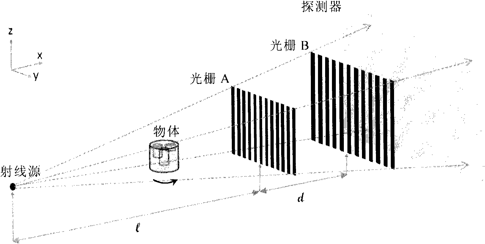
[0124] In CT imaging mode, the detected object should be able to rotate relative to other parts of the system such as grating and ray source. Therefore, a rotating device is provided for the detected object to rotate the detected object, or a rotating structure is provided so that the detected object does not move while the ray source and the grating rotate relatively. The above-mentioned rotating device or rotating structure is not shown in the figure, and it can have various implementations according to the existing common knowledge. Also, such a rotation device or structure is connected to the control portion of the imaging system such that the rotation is adapted to the motion of the system (stepping and otherwise). According to the principle of phase-contrast CT imaging, the CT imaging of an object using the system of the present invention can obtain X-ray plane imaging for each projection direction of the object, and then perform relevant CT reconstruction processing on ...


PUM

PropertyMeasurementUnit
thicknessaaaaaaaaaa

Abstract

The invention relates to a system and a method for X-ray grating contrast imaging. The system comprises an X-ray launching device, a first absorption grating, a second absorption, a detecting unit, a data processing unit and an imaging unit, wherein the X-ray launching device is used for launching X-ray beams to a detected article; the first absorption grating and the second absorption grating are positioned in the launching direction of the X-ray beams, and the X-ray refracted by the detected article forms X-ray signals with different intensity by the first absorption grating and the second absorption grating; the detecting unit is used for receiving the X-ray signals with changeable intensity and converting the X-ray signals into electric signals; and the data processing unit is used for processing and extracting the refraction angle information in the electric signals and calculating the pixel information through the refraction angle information; the imaging unit is used for constructing the image of the article. In addition, a rotating structure can also be utilized to rotate the article to realize a CT imaging mode so as to obtain refraction angles in a plurality of projection directions and the corresponding images and calculate the refraction index tomography image of the detected article by CT reconstruction algorithm. The system and the method adopt the common X-ray machine and the grating above a period of ten micron magnitude to realize the contrast imaging of a decimeter magnitude like viewing field.

Description

technical field [0001] The invention relates to the field of perspective imaging, in particular to the photographic imaging and CT imaging of objects with X-rays. Background technique [0002] Traditional X-ray imaging technology uses the attenuation properties of X-rays by material materials to non-destructively inspect the internal structure of objects. Conventional X-ray imaging techniques are especially effective if the density of the structural composition of the various parts inside the object differs significantly. However, substances made of light elements such as hydrogen, carbon, nitrogen and oxygen are weak absorbers for X-rays, so the detailed structure inside them can hardly be seen with traditional X-ray imaging techniques. Even with other auxiliary means, such as imprinting contrast agents on biological tissues, it is difficult to obtain clear images. [0003] In the mid-1990s, due to the development of the third-generation synchrotron radiation facility, ha...

Claims


Application Information

Patent Timeline
Patent Type & Authority Applications(China)
IPC IPC(8): G01N23/083
CPCA61B6/484
Inventor 康克军黄志峰张丽陈志强李元景刘以农赵自然刑宇翔
Owner NUCTECH CO LTD
Why Eureka
Try Eureka