Automobile battery thermal management system and working method thereof

A technology of battery thermal management and working method, applied in the field of vehicle battery thermal management system, can solve the problems of power battery failure, hidden danger of vehicle operation safety, performance degradation, etc., and achieve the effect of prolonging service life, ensuring safety, and reducing use cost

Inactive Publication Date: 2009-11-11
UNITED AUTOMOTIVE ELECTRONICS SYST
View PDF0 Cites 42 Cited by
  • Summary
  • Abstract
  • Description
  • Claims
  • Application Information

AI Technical Summary

Problems solved by technology

The power battery is composed of multiple battery cells connected in series and parallel. The current power battery cells cannot work normally in extreme low temperature (less than -30°C) and extreme high temperature (greater than 50°C) environments, resulting in the use of power batteries as the The vehicle with the energy source cannot work normally at this time, so that the vehicle cannot meet the requirements of all-weather operation. Compared with traditional vehicles, its use has greater limitations
[0004] In addition, the current power battery is composed of dozens or hundreds of battery cells connected in series and parallel. If the performance of a certain battery decreases due to aging or other reasons, the performance of the entire power battery will drop sharply. If a certain battery If a single unit fails, it may cause the failure of the entire power battery
This brings a lot of trouble to the maintenance of the power battery: if any single battery cell fails, the entire battery pack must be replaced. At the same time, due to the high price of the battery itself, the maintenance cost of the battery remains high.
There are many reasons for the inconsistent performance of battery

Method used


Image

  • Automobile battery thermal management system and working method thereof

Examples


Embodiment Construction

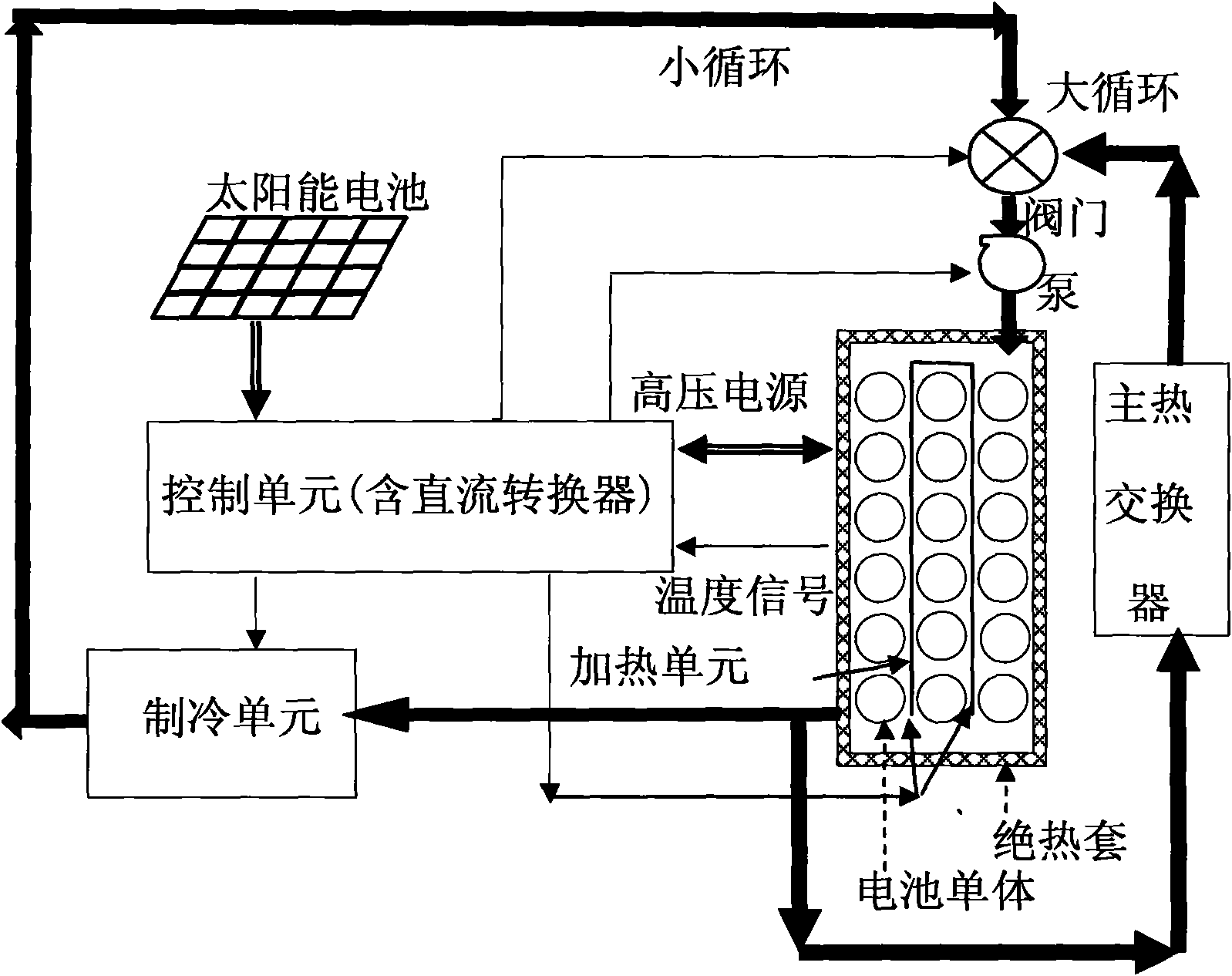
[0019] The structure of the vehicle battery thermal management system of the present invention is shown in the accompanying drawings, including:

[0020] A battery pack, the battery pack is provided with battery units electrically connected to each other, the battery unit is composed of one or a plurality of battery cells electrically connected to each other, the battery pack is sealed and packaged, and most of each battery unit or All are surrounded by voids filled with cooling liquid, and all voids filled with cooling liquid are connected to each other, the voids filled with cooling liquid are provided with temperature sensors, and the battery pack is provided with inlets of cooling liquid and an outlet, the battery pack is provided with a heating unit immersed in the cooling liquid;

[0021] The inlet and outlet of the cooling liquid are respectively connected to two pipelines to form two cycles, namely a large cycle and a small cycle. The large cycle is the inlet and outle...


PUM


Abstract

The invention discloses an automobile battery thermal management system, which comprises a battery pack consisting of battery units, and cooling fluid is filled among the battery units; an inlet and an outlet of the cooling fluid are connected to two pipelines respectively so as to form a big cycle and a small cycle; the big cycle is connected with a main heat exchanger, the small cycle is connected with a refrigeration unit, a position in which the big cycle pipeline is connected with the small cycle pipeline is provided with a valve, and the big cycle pipeline and the small cycle pipeline are provided with a pump for driving the cooling fluid to flow; in addition, the system also comprises a control unit for acquiring signals of a temperature sensor in the battery pack and controlling other components. The invention also discloses a method for the automobile battery thermal management system, which can ensure that the temperature of the cooling fluid in the battery pack is constant within a proper range. The system and the method can make a battery in a proper temperature environment so as to prolong the service life of a battery system, ensure the safety of the battery system and reduce the using cost of the battery system.

Description

technical field [0001] The invention relates to a heat management system for a vehicle battery, and also relates to a working method of the heat management system for a vehicle battery. Background technique [0002] In recent years, due to the pressure of energy costs and the increasing emphasis on environmental protection by the government and consumers, hybrid vehicles and electric vehicles have attracted the attention of many automobile manufacturers due to their advantages of greatly reducing or eliminating exhaust emissions and reducing energy consumption. And have invested heavily in research and development and promotion. However, power battery technology has greatly restricted the promotion of hybrid vehicles and electric vehicles, and has become a bottleneck in the development of new energy vehicles. [0003] As an energy storage device, the power battery plays an extremely critical role in hybrid electric vehicles and electric vehicles, and its performance greatly...

Claims


Application Information

Patent Timeline
IPC IPC(8): H01M10/50H01M10/44H02J7/00G05B19/04G05D23/02H01M10/613H01M10/625H01M10/6567
CPCY02E60/12Y02E60/10
Inventor 卢万成陈贤章陈长飞
Owner UNITED AUTOMOTIVE ELECTRONICS SYST
Why Eureka
Try Eureka