Anti-vacuum semi-solid states stirring soldering method of magnesium alloy and composite material thereof

A semi-solid mixing and composite material technology, which is applied in welding equipment, metal processing equipment, manufacturing tools, etc., can solve the problems of semi-solid connection technology that have not been reported, and achieve the effect of overcoming adverse consequences, avoiding softening, and improving performance

Inactive Publication Date: 2009-11-18
CHONGQING UNIV OF TECH
View PDF3 Cites 9 Cited by
  • Summary
  • Abstract
  • Description
  • Claims
  • Application Information

AI Technical Summary

Problems solved by technology

As mentioned above, there is no report on the semi-solid connection technology with the above characteristics at home and abroad.

Method used


Image

  • Anti-vacuum semi-solid states stirring soldering method of magnesium alloy and composite material thereof
  • Anti-vacuum semi-solid states stirring soldering method of magnesium alloy and composite material thereof
  • Anti-vacuum semi-solid states stirring soldering method of magnesium alloy and composite material thereof

Examples


Embodiment 1

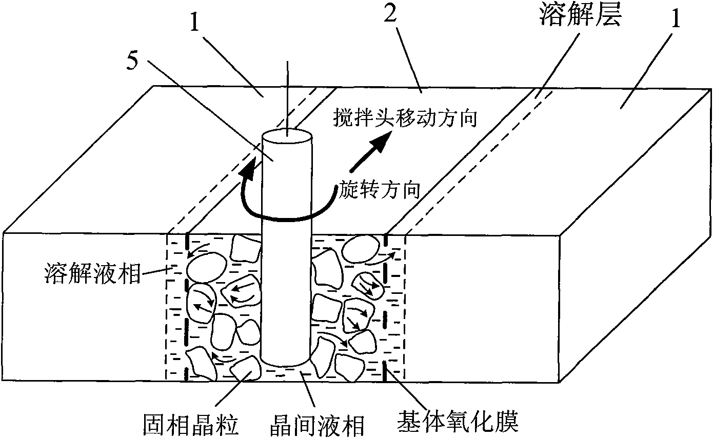
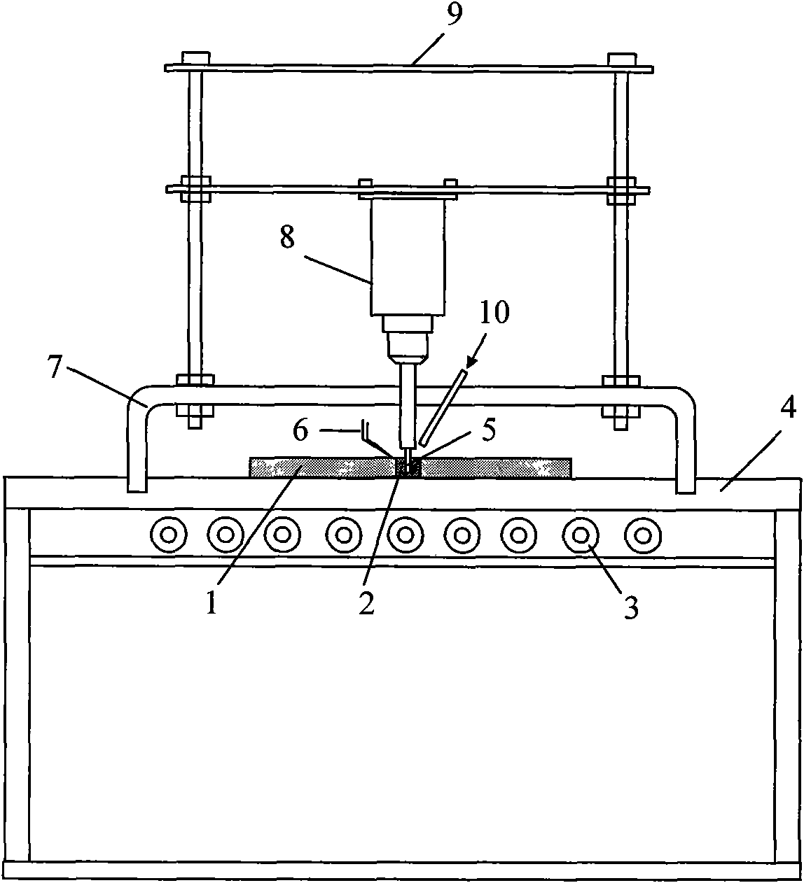
[0034]Example 1: Mount the magnesium alloy weldment 1 on the welding platform 4, and place the Mg-Zn medium temperature solder 2 on the two surfaces to be welded. The solder 2 can be in the form of a sheet, a square column, a plating layer or sprayed on the welding platform in advance. Welding surface. The welding piece is heated by the resistance heater 3, and the heating temperature is between 380-430°C, such as 380°C, 400°C, 420°C, 430°C, so that the solder 2 is partially melted. Immediately start the rotating sliding device, the orbital sliding platform 7 drives the stirring head 5 to move, and the rotating motor 8 mounted on the motor support 9 drives it to rotate. The rotation speed is 150-300 rpm, such as 150 rpm, 180 Revolution / min, 230 revolutions / min, 280 revolutions / min, 300 revolutions / min, the temperature is constant during the rotation, the longitudinal movement speed of the stirring head 5 parallel to the weld seam is 0.5-2cm / min, such as 0.5cm / min , 1.0cm / min, 1.5c...

Embodiment 2

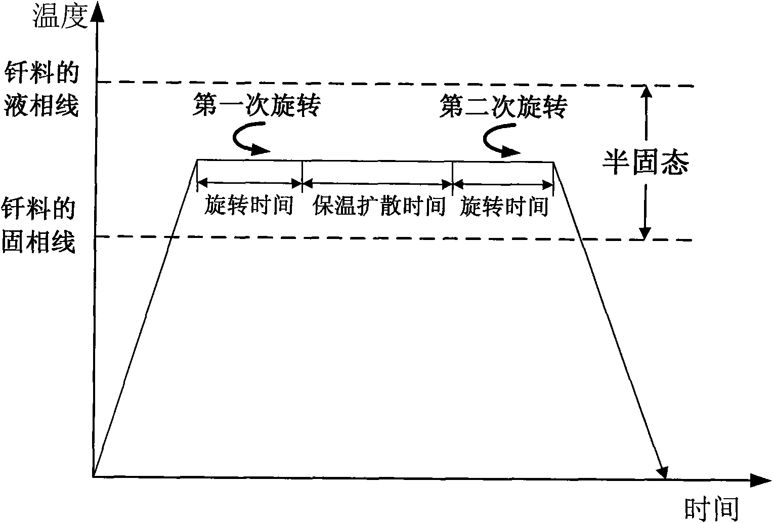
[0035] Example 2. The second embodiment of the present invention is based on the first embodiment. After one rotation, the holding time is 1-2 minutes, such as 1 minute, 1.5 minutes, 1.8 minutes or 2 minutes, so that The weldment 1 is further dissolved. Then, start the rotary sliding device (secondary rotation) again, the rotation speed is 100-150 rpm, such as 100 rpm, 120 rpm, 140 rpm or 150 rpm, the stirring head slides in the opposite direction, The moving speed is 1-1.5cm / min, such as 1cm / min, 1.2cm / min or 1.5cm / min. When the stirring head moves to the initial end of the weld, stop rotating, lift the stirring head, and keep it warm for 15-30 minutes, such as 15 minutes, 20 minutes, 25 minutes or 30 minutes, and cool down with the furnace.


PUM


Abstract

The invention provides an anti-vacuum semi-solid states stirring soldering method of magnesium alloy and composite material thereof, which comprises the following steps of: a weldment taking the magnesium alloy or the composite material thereof as a parent metal is arranged and blocked on a welding platform and medium temperature brazing filler metal is put on two surfaces to be welded; the weldment is heated in the temperature of 380 to 430 DEG C to cause that the solid phase ratio of the brazing filler metal is between 50 to 80%; hereupon, a rotational sliding device is started; the rotary speed is 150 to 300 r/m; the temperature is constant; a stirring head is parallel to the longitudinal movement speed of 0.5-2cm/min of a welding line; when the stirring head moves to the terminal of the welding line, the rotational sliding stops; the holding time is 1 to 5 minutes so that the weldment is further dissolved; the rotational device is started again; the rotary speed is 20 to 150 r/m; the stirring head slides in a negative direction; the movement speed is 1 to 2 cm/min. When the stirring head moves to the initial end of the welding line, the rotary stops; the stirring head is lifted; the holding temperature is 5-30 minutes, and a furnace cools. The method can realize the low cost, high efficient, high quality welding of the magnesium alloy and the composite material thereof.

Description

Technical field [0001] The invention relates to a welding method of magnesium alloy and its composite material. Background technique [0002] Magnesium alloy and its composite materials are currently the lightest structural materials in industrial applications. Magnesium alloy and its composite materials not only have higher specific strength and specific stiffness, but also have excellent heat dissipation performance, electromagnetic shielding performance, shock absorption performance and mechanical properties. Processing performance, especially in the aviation, automotive, and electronic industries has broad application prospects. Because magnesium alloy has the characteristics of low melting point, strong oxidation and wide crystallization temperature range, it is easy to oxidize and burn during the welding heating process, and it is easy to produce cracks, pores, cavities, slag inclusion and deformation, etc., so the magnesium alloy Welding forming is one of the current resea...

Claims


Application Information

Patent Timeline
Patent Type & Authority Applications(China)
IPC IPC(8): B23K1/00
Inventor 许惠斌叶宏伍光凤李晖李春天
Owner CHONGQING UNIV OF TECH
Why Eureka
Try Eureka