
High-speed linear drive mechanism for hectograph

A linear drive mechanism and offset printing technology, applied in printing machines, rotary printing machines, printing, etc., can solve problems affecting printing quality and precision, short service life of chains, and cylinder stroke limitations, etc., to achieve uniform speed and excellent performance , the effect of easy maintenance

Active Publication Date: 2011-09-21
广州互通气动机器工程有限公司
View PDF0 Cites 0 Cited by
  • Summary
  • Abstract
  • Description
  • Claims
  • Application Information

AI Technical Summary

Problems solved by technology

[0003] The first type is the chain drive driven by the sprocket. The transmission structure of the sprocket chain is relatively simple, the price is relatively cheap, and it is easy to purchase, but the accuracy is relatively poor, the service life of the chain is not long, and printing positioning is difficult;
[0004] The second type is synchronous belt driven synchronous wheel drive, synchronous wheel synchronous belt transmission is relatively simple, the price is relatively cheap, easy to purchase, but the force is not large, the life is not long, limited by the length of the synchronous belt, high-speed movement will Vibration will affect printing quality and accuracy;
[0005] The third type is linear cylinder drive, which can only do reciprocating motion and is limited by the stroke of the cylinder;
[0006] The fourth type is cam drive. The cam drive mostly adopts a closed cam curve, and the bearing reciprocates in the cam groove, with uneven speed and short stroke.

Method used


Image

  • High-speed linear drive mechanism for hectograph
  • High-speed linear drive mechanism for hectograph
  • High-speed linear drive mechanism for hectograph

Examples


Embodiment

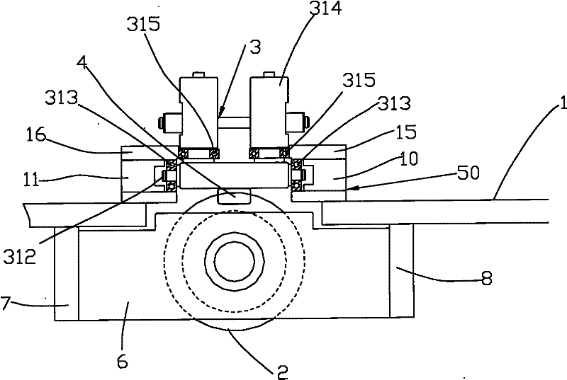
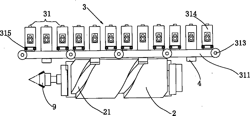
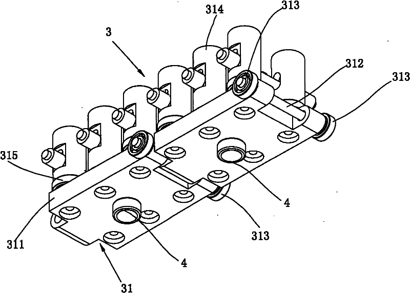
[0026] see Figure 1 to Figure 7 As shown, a linear drive mechanism for offset printing includes a frame 1 and a cam 2 placed below the frame 1. A transmission gear 9 for power transmission is provided at the front end of the cam 2. Along the top of the outer surface of the cam 2 The bottom end is provided with a cam curve groove 21, and a moving trolley group 3 is also arranged on the frame 1. A slide rail 50 is provided between the moving trolley group 3 and the frame 1. There are a plurality of roller bearings 4 that are spaced apart and matched with the cam curve groove 21. When the external power is input to the transmission gear 9, the gear 9 rotates and drives the cam 2 to rotate, and the cam 2 pushes the roller bearing 4 on the cam curve. Sliding in the groove 21, the roller bearing 4 will drive the moving trolley group 3 to run in the slide rail 50 simultaneously, finally forms the high-speed linear movement of the moving trolley group.

[0027] The linear drive mech...


PUM


Abstract

The invention discloses a linear drive mechanism for hectograph, comprising a machine frame and a cam arranged under the machine frame, wherein, the front end of the cam is provided with a transmission gear for power transmission, and a cam slot is arranged along the top end and the bottom end of the outer surface of the cam; a moveable cart group is arranged on the machine frame, a sliding trackis arranged between the moveable cart group and the machine frame, and a plurality of roller bearings which are kept at intervals and are matched with the cam slot are arranged on the lower bottom surface of the moveable cart group; and when power is transmitted into a transmission gear, the transmission gear drives the cam to rotate, and the cam pushes the roller bearings to run in the sliding track along with the moveable cart group. The mechanism can connect a plurality of cams to simultaneously drive multiple groups of moveable cart group for multiple times of printing, and has the advantages of high transmission accuracy, accurate positioning, high speed, long service life, low noise, simple structure, easy production, low cost, high assembly efficiency, convenient repair, installation and disassembly, safe and reliable installation, reasonable structure, excellent performance, and high convenience and practicability.

Description

technical field [0001] The invention relates to the technical field of offset printing, in particular to a linear drive mechanism for offset printing of bottle caps. Background technique [0002] In the current offset printing of bottle caps, the linear drive mechanism usually adopts four drive structures: [0003] The first type is the chain drive driven by the sprocket. The transmission structure of the sprocket chain is relatively simple, the price is relatively cheap, and it is easy to purchase, but the accuracy is relatively poor, the service life of the chain is not long, and printing positioning is difficult; [0004] The second type is synchronous belt driven synchronous wheel drive, synchronous wheel synchronous belt transmission is relatively simple, the price is relatively cheap, easy to purchase, but the force is not large, the life is not long, limited by the length of the synchronous belt, high-speed movement will Vibration will affect printing quality and acc...

Claims


Application Information

Patent Timeline
Patent Type & Authority Patents(China)
IPC IPC(8): B41F17/24
Inventor 黎国明
Owner 广州互通气动机器工程有限公司
Learn More