Delay fault testing method and system oriented to the application of FPGA

A delayed fault, application-oriented technology, applied in electronic circuit testing, digital circuit testing, electrical measurement, etc., can solve problems such as changing circuit structure and reducing circuit performance, so as to simplify generation steps, improve controllability, and fault coverage high effect

Inactive Publication Date: 2009-11-18
PEKING UNIV +1
View PDF0 Cites 13 Cited by
  • Summary
  • Abstract
  • Description
  • Claims
  • Application Information

AI Technical Summary

Problems solved by technology

Some people propose to implement MUX logic through idle LUT, so as to replace MUX for testing, but this metho

Method used


Image

  • Delay fault testing method and system oriented to the application of FPGA
  • Delay fault testing method and system oriented to the application of FPGA
  • Delay fault testing method and system oriented to the application of FPGA

Examples


Embodiment Construction

[0042] The application-oriented FPGA delay fault testing method and system proposed by the present invention are described as follows in conjunction with the accompanying drawings and embodiments.

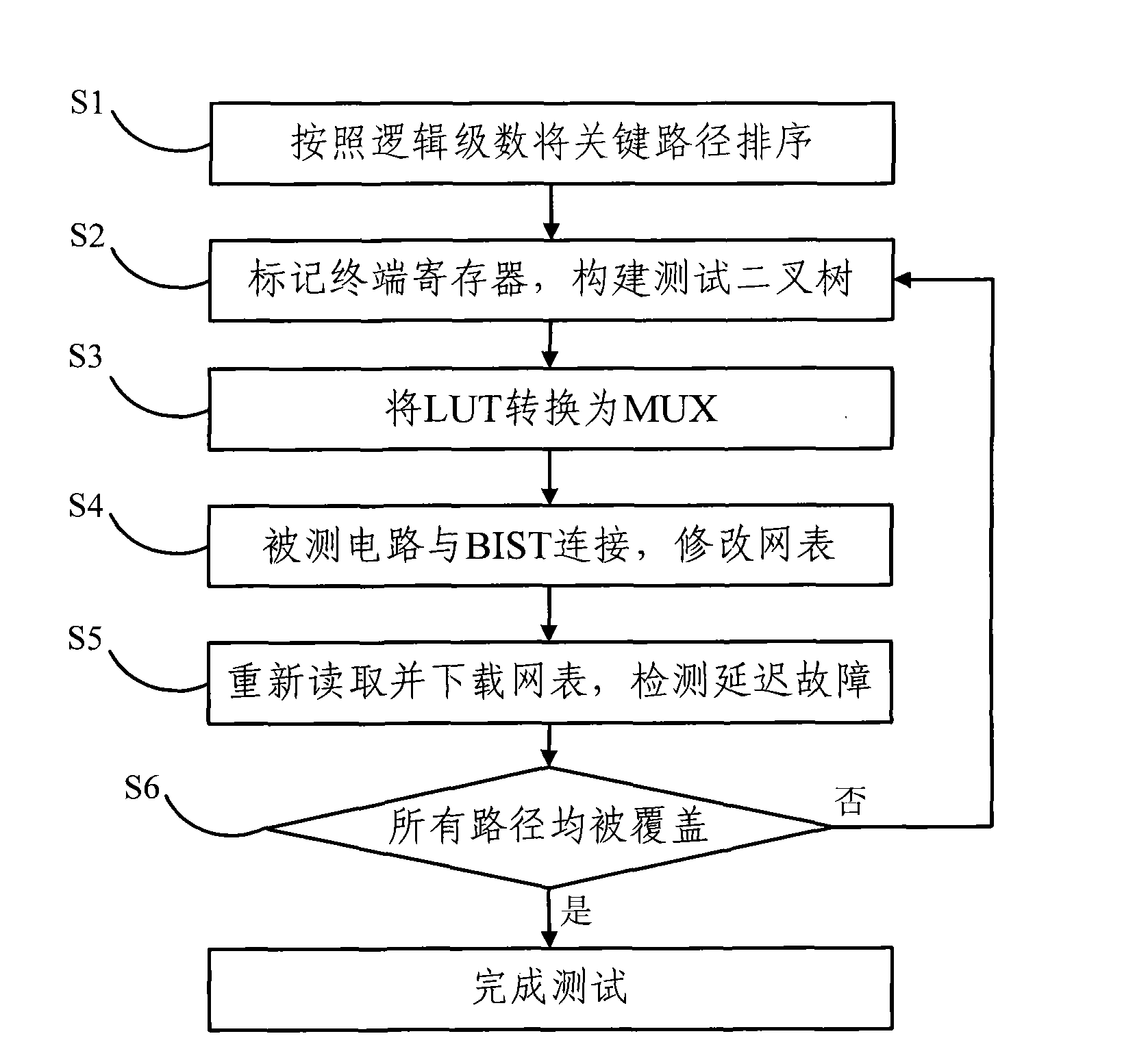
[0043] Such as figure 1 As shown, in the application-oriented FPGA delay fault testing method of the present invention, at first, the critical path needs to be determined according to the clock frequency required by the circuit design, and all paths whose delay is greater than 70% of the clock cycle are all defined as critical paths. Then proceed to the following steps

[0044] S1. Determine the critical paths to be tested according to the clock cycle required by the circuit design, and sort all the critical paths according to the logical progression;

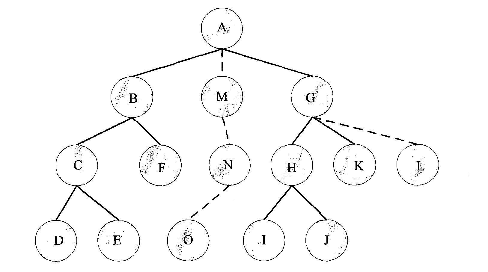
[0045]S2. Take the terminal register of the critical path with the highest logic level as the root node, mark the terminal register as measured, and select the second measured path from all paths whose terminals are the register an...


PUM


Abstract

The invention discloses a delay fault testing method and a system oriented to an application of FPGA, the method comprise the following steps: sequencing all the critical paths according to the a logical progression; taking a terminal register of the critical path with the highest logical progression as a root node and selecting a second path to be tested from the path of which all the terminals is the register and a child node dose not belong to the critical path to form a testing binary tree; modifying LUT allocation function of all the paths to be tested which form testing binary tree to MUX logical function; connecting BIST circuit with the circuit to be tested and modifying a network list; reading and downloading the modified network list containing BIST circuit and the circuit to be tested by utilizing a design tool once again, testing whether the delay fault exists or not; repeating the above steps until all the critical paths are covered and completing the testing. In the invention, the highest fault coverage can be reached under the condition of unchanging original design of using logical unit and under the premise that the logical types used to FPGA design are not limited.

Description

technical field [0001] The invention relates to the technical field of delay fault testing, in particular to an application-oriented FPGA delay fault testing method and system. Background technique [0002] FPGA (Field Programmable Gate Array, Field Programmable Gate Array) has the advantages of short application design and development cycle and reconfigurability. At present, FPGA is not only used for the verification of prototype design, but also used to realize some or even main functions in electronic systems in many application fields. Some of these application areas, such as medical equipment and avionics, have high requirements on the reliability of the system, which makes FPGA testing of special importance for these applications. [0003] Usually, in order to ensure the reliability of the circuit, the FPGA application will test all resources in the FPGA for fixed faults. However, as the size of FPGA devices continues to decrease, the frequency at which circuits can ...

Claims


Application Information

Patent Timeline
IPC IPC(8): G01R31/317G01R31/3177
Inventor 冯建华孙博韬林腾徐文华
Owner PEKING UNIV
Why Eureka
Try Eureka