Supercharge Your Innovation With Domain-Expert AI Agents!

Color filter substrate, manufacturing method, and liquid crystal display panel

A color filter technology and a manufacturing method, applied in optics, optomechanical equipment, nonlinear optics, etc., can solve the problems of poor PI climbing ability, no PI layer, light leakage, etc., to avoid embedded overlap , The effect of reducing the production cycle and reducing the production cost

Active Publication Date: 2012-02-08
KUSN INFOVISION OPTOELECTRONICS
View PDF5 Cites 0 Cited by
  • Summary
  • Abstract
  • Description
  • Claims
  • Application Information

AI Technical Summary

Problems solved by technology

In the actual production process, due to the limitations of the factory's process capability and the shrinkage rate of the color-resist material, the color blocking difference in the overlapping area is relatively large, and the so-called "bull horns"15 are formed in the overlapping area, which makes the In the subsequent process of printing the PI layer, the climbing ability of PI in this area is not good, and even the PI layer is not formed, resulting in a difference between the alignment of the liquid crystal molecules in the liquid crystal layer close to this area and the effective display area corresponding to the color resist layer 13. The initial arrangement of molecules is wrong, and because this area is not blocked by the black matrix, there will be light leakage

Method used


Image

  • Color filter substrate, manufacturing method, and liquid crystal display panel
  • Color filter substrate, manufacturing method, and liquid crystal display panel
  • Color filter substrate, manufacturing method, and liquid crystal display panel

Examples


no. 1 example

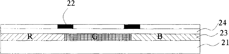
[0051] The sectional view of the color filter substrate of the first embodiment of the present invention is as follows figure 2 As shown, in this embodiment, the color filter substrate mainly includes: a substrate 21 , a black matrix layer 22 , a color resist layer 23 and a transparent conductive layer 24 . The substrate 21 is transparent, and may be a hard substrate made of glass, quartz, etc., or a flexible substrate made of plastic, polymer material, or the like. The color-resist layer 23 is directly formed on the substrate 21. Same as the prior art, the different areas of the color-resist layer 23 are respectively set as red (R), green (G), and blue (B) color-resist. The light is displayed as red, green and blue respectively, and the red (R), green (G), and blue (B) color resists are closely adjacent or there are gaps. The transparent conductive layer 24 is located on the color resist layer 23, and the material of the transparent conductive layer 24 is required to be a t...

no. 2 example

[0066] The sectional view of the color filter substrate of the second embodiment of the present invention is as follows Figure 4 As shown, in this embodiment, the color filter substrate mainly includes: a substrate 41 , a black matrix layer 42 , a color resist layer 43 and a transparent conductive layer 44 . The materials selected for the components of the color filter substrate in this embodiment are the same as those in the first embodiment, and will not be repeated here. Compared with the first embodiment, the difference of the color filter substrate shown in the second embodiment is that the black matrix layer 42 is directly on the substrate 41, the color resist layer 43 is on the black matrix layer 42, and the transparent conductive layer 44 is on the on the color resist layer 43 .

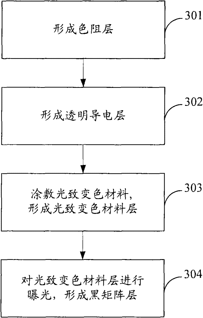
[0067] In this embodiment, the process flow of the manufacturing method of the color filter substrate is as follows Figure 5 As shown, it mainly includes the following steps:

[0068] St...

no. 3 example

[0077] The sectional view of the color filter substrate of the third embodiment of the present invention is as follows Figure 6 As shown, in this embodiment, the color filter substrate mainly includes: a substrate 61 , a black matrix layer 62 , a color resist layer 63 and a transparent conductive layer 64 . The materials selected for the components of the color filter substrate in this embodiment are the same as those in the first embodiment, and will not be repeated here. Compared with the first embodiment, the difference of the color filter substrate shown in the third embodiment is that the color resist layer 63 is located on the substrate 61, the black matrix layer 62 is located on the color resist layer 63, and the transparent conductive layer 64 is located on the black matrix layer 62.

[0078] In this embodiment, the process flow of the manufacturing method of the color filter substrate is as follows Figure 7 As shown, it mainly includes the following steps:

[007...


PUM


Abstract

The present invention proposes a method for manufacturing a color filter substrate. The black matrix layer is made of a photochromic material, and the black matrix layer is formed by exposing the photochromic material coated on the entire layer, so it does not need to be developed to remove the black matrix layer. In the area between each black matrix, the embedded overlapping of the color resist layer and the black matrix layer is avoided. The invention also proposes a color filter substrate and a liquid crystal display panel manufactured by the above method. Since there is no "horn" in the overlapping area of ​​the color resist layer and the black matrix layer, there will be no light leakage caused by poor climbing ability of PI or no PI layer formed in the subsequent process; The production cycle and production cost of the color filter substrate are shortened; and when bright spots appear in the pixels of the manufactured color filter substrate, it can be repaired by methods such as ultraviolet light irradiation.

Description

technical field [0001] The invention relates to the technical field of liquid crystal display, in particular to a color filter substrate, a manufacturing method and a liquid crystal display panel. Background technique [0002] Liquid Crystal Display (LCD) not only has the characteristics of being light, thin, and small, but also has the advantages of low power consumption, no radiation, and relatively low manufacturing cost, so it currently occupies a dominant position in the field of flat panel display. Liquid crystal displays are ideally suited for use in desktop computers, palmtop computers, personal digital assistants (Personal Digital Assistant, PDA), cellular phones, televisions, and a variety of office automation and audio-visual equipment. [0003] The liquid crystal display panel is the main component of the liquid crystal display. The current mainstream liquid crystal display panel is composed of a thin film transistor (Thin Film Transistor, TFT) substrate and anot...

Claims


Application Information

Patent Timeline
Patent Type & Authority Patents(China)
IPC IPC(8): G02F1/1335G03F7/00G02F1/133
Inventor 邱郁雯苏子芳
Owner KUSN INFOVISION OPTOELECTRONICS
Features
  • R&D
  • Intellectual Property
  • Life Sciences
  • Materials
  • Tech Scout
  • Unparalleled Data Quality
  • Higher Quality Content
  • 60% Fewer Hallucinations
Learn More