
Compensator transformer type voltage regulation method and device

Inactive Publication Date: 2009-11-18
CHINA AGRI UNIV
View PDF0 Cites 17 Cited by
  • Summary
  • Abstract
  • Description
  • Claims
  • Application Information

AI Technical Summary

Problems solved by technology

[0004]However, the above-mentioned voltage regulation methods have certain disadvantages. The output voltage of the thyristor phase-controlled voltage regulation method has distortion and large harmonics, and is not suitable for With capacitively compensated load
The disadvantage of the inductive voltage regulation method is that it has a large volume and weight, and requires multiple sets of contactors or motor drive mechanisms, which increases reactive power consumption.
The switching process of the self-coupling winding tap-type voltage regulation method needs to be strictly controlled, the load cannot be opened, and the taps cannot be short-circuited, and it is difficult to realize reliable switching of the taps, and there is an adjustment shock
However, when the switching switch of the voltage compensation type voltage regulation method uses a contactor, there is a high impact voltage during the switching process of the switch, and when the switching switch uses a thyristor, there is a conduction loss.

Method used


Image

  • Compensator transformer type voltage regulation method and device
  • Compensator transformer type voltage regulation method and device
  • Compensator transformer type voltage regulation method and device

Examples


Embodiment Construction

[0021] The technical solutions of the present invention will be described in further detail below with reference to the accompanying drawings and embodiments.

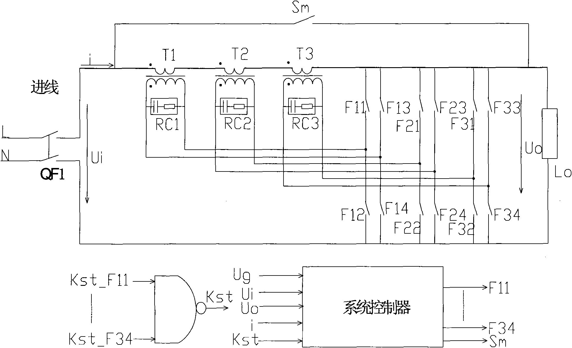
[0022] figure 1 It is a structural schematic diagram of an embodiment of the compensation transformer type voltage regulating device of the present invention, such as figure 1 As shown, this embodiment provides a compensating transformer-type voltage regulating device, which can be divided into two parts, the main circuit and the system controller. The main circuit is connected to the power terminals L and N through the air switch QF1. The main circuit can include a compensating transformer group composed of compensating transformers T1, T2 and T3, and a switch array composed of composite switches F11, F12, F13, F14, F21, F22, F23, F24, F31, F32, F33 and F34 . Among them, the compensation transformer group is connected in series between the power supply terminal L and the load L O Between and N, the composite switch...


PUM


Abstract

The invention discloses a compensator transformer type voltage regulation method and a device, wherein, the device comprises a compensator transformer bank, combination switches and a system controller; the compensator transformer bank is connected between a power supply and a load in series, and each terminal of a high-voltage winding of every compensator transformer is controlled by the two combination switches alternately; the switching state of the combination switch is controlled by the system controller; the system controller is used for determining the switching combination of the combination switches according to the output voltage of the load and the expected voltage input by the user, and for sending switching signals to the combination switches according to the switching combination. The invention also provides the compensator transformer type voltage regulation method. The invention can eliminate the overvoltage surge of the voltage regulation device generated in the switching process, thus effectively reducing the conduction loss.

Description

technical field [0001] The invention relates to an AC voltage regulation technology, in particular to a compensating transformer type voltage regulation method and device. Background technique [0002] In the low-voltage distribution network including single-phase 220v lines and three-phase 380v lines, the voltage fluctuates due to grid fluctuations and frequent load switching. If the load voltage is too high, it will increase the loss and affect the load insulation, such as motors, lamps and other loads; if the load voltage is too low, some loads may not work properly. When the load works below the rated voltage, it can produce the effect of saving electricity. Therefore, in order to achieve the purpose of protecting electrical appliances and reducing losses, it is necessary to regulate the line voltage in the distribution network. [0003] In the existing technology, in addition to adjusting the tap changer of the distribution transformer to realize line voltage regulati...

Claims


Application Information

Patent Timeline
Patent Type & Authority Applications(China)
IPC IPC(8): G05F1/253
Inventor 杜海江唐云峰王文成杨仁刚赵凤展
Owner CHINA AGRI UNIV
Learn More