
Laser processing control device and laser processing device

A technology for laser processing and control devices, applied in lasers, auxiliary devices, metal processing, etc., can solve the problems of laser penetration, abnormal hole diameter, inability to open holes, etc., and achieve the effect of accurate laser power

Inactive Publication Date: 2009-11-25
MITSUBISHI ELECTRIC CORP
View PDF1 Cites 6 Cited by
  • Summary
  • Abstract
  • Description
  • Claims
  • Application Information

AI Technical Summary

Problems solved by technology

[0003] In the above-mentioned laser processing device, if the total value of the energy (intensity) of the laser light irradiated on one processing hole deviates from the specified value, the quality of the hole formed on the printed circuit board will deteriorate.
For example, when the total energy value of the laser deviates from the specified value, the diameter of the formed hole is abnormal, the hole cannot be drilled, the laser penetrates through the hole, and processing debris remains.

Method used


Image

  • Laser processing control device and laser processing device
  • Laser processing control device and laser processing device
  • Laser processing control device and laser processing device

Examples


Embodiment approach 1

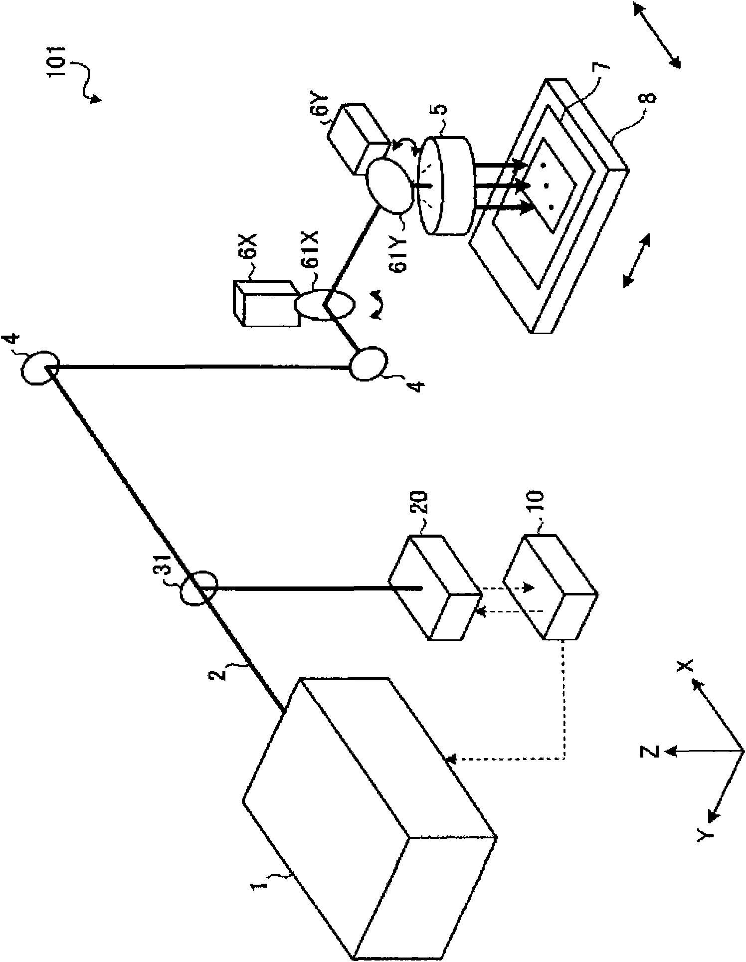
[0025] figure 1 It is a figure which shows the schematic structure of the laser processing apparatus concerning Embodiment 1 of this invention. The laser processing device 101 is a device that performs drilling processing or the like on the workpiece by irradiating pulsed laser light on the workpiece such as a printed board, and is controlled by the laser processing control device 10 .

[0026] The laser processing device 101 has a laser oscillator 1, a reflection mirror 4, an fθ lens 5, a galvano scanner 6X, 6Y, a galvano scanner 61X, 61Y, an XY table 8, a partial reflection mirror (partial transmission mirror) 31, and An integral signal calculation device 20 , and a laser processing control device 10 . The laser oscillator 1 emits pulsed laser light (laser light 2 ) with a width of, for example, 1 to 100 μsec at an oscillation frequency of, for example, 100 to 10000 Hz, and enters the mirror 4 via the partial reflection mirror 31 . Part of the laser light 2 emitted from th...

Embodiment approach 2

[0071] Below, refer to Figure 10 ~ Figure 12 Embodiment 2 of the present invention will be described. In Embodiment 2, the laser processing control device 10 performs calculations using software, corrects the integrated signal a3 to a correct integrated signal (integrated signal in consideration of temperature drift), and uses the corrected integrated signal (integrated signal a4 described later). Calculate the actual energy of the pulsed laser.

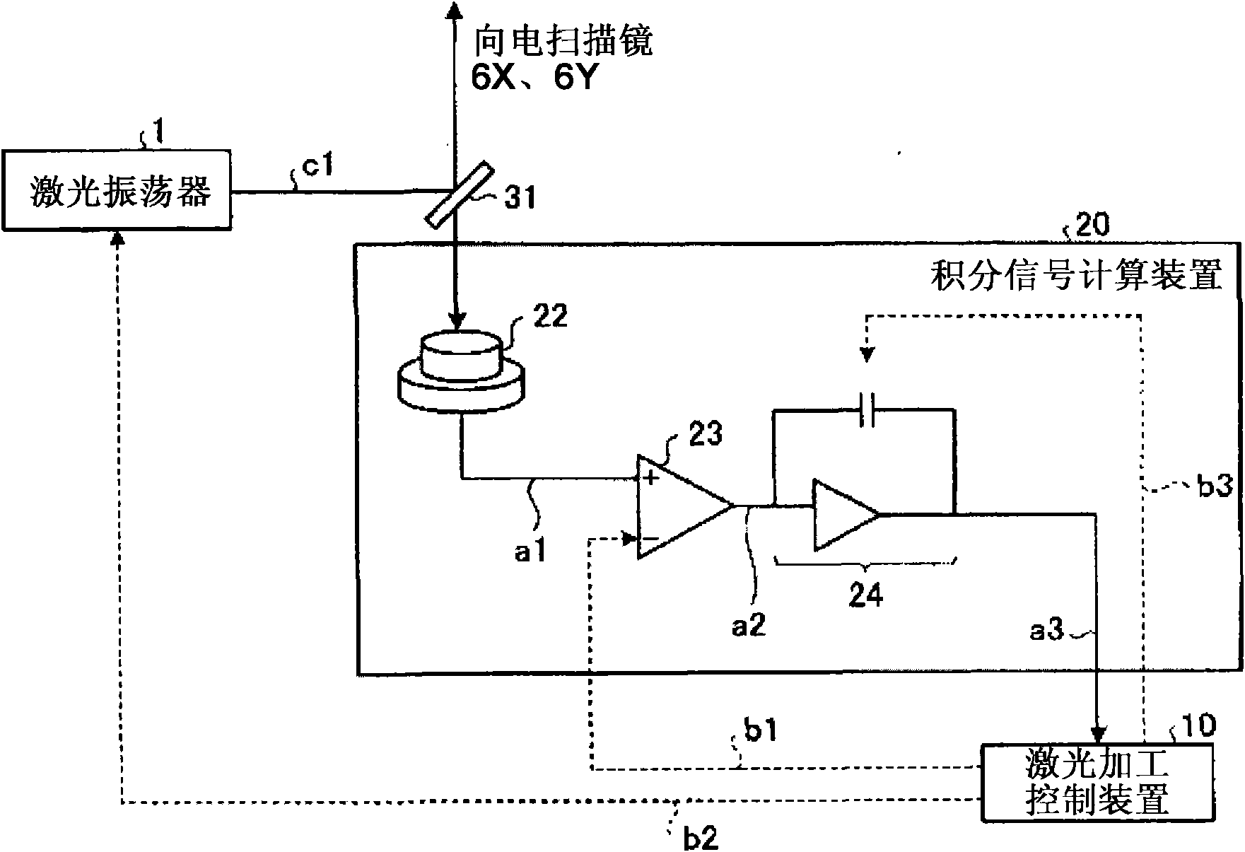
[0072] Figure 10 It is a figure which shows the structure of the integrated signal measurement apparatus concerning Embodiment 2. exist Figure 10 Among the various constituent elements, for the implementation and figure 2 Components having the same functions as those of the integrated signal calculation device 20 in the first embodiment shown are denoted by the same reference numerals, and repeated explanations are omitted.

[0073] The integrated signal calculation device 20 is configured to include an infrared sensor 22 an...


PUM


Abstract

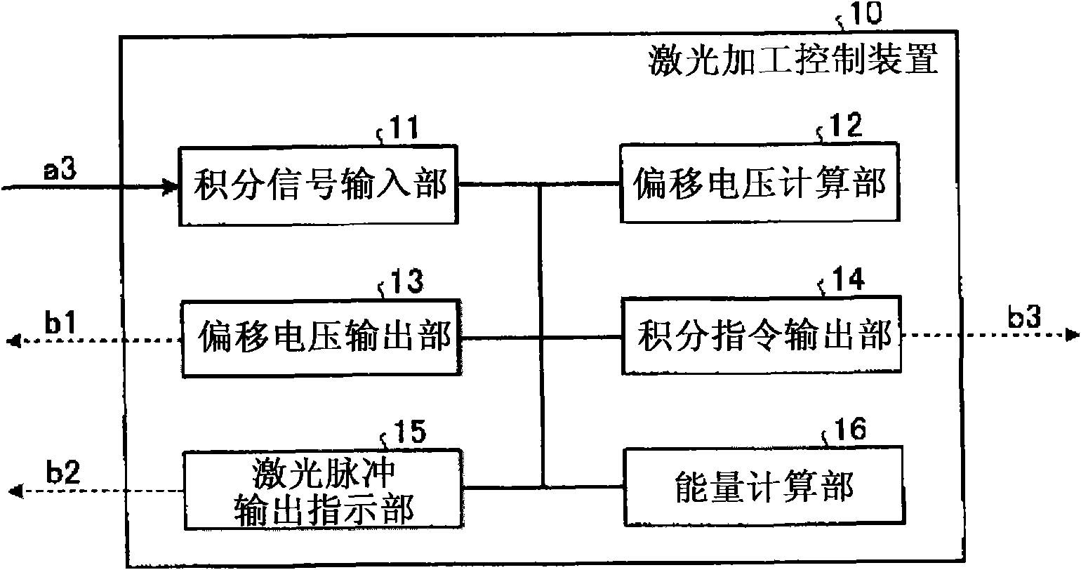
The invention obtains a laser processing control device for controlling the radiation of pulse laser and a laser processing device thereof. The laser processing control device has: a laser power measuring part, measuring the laser power of pulse laser; an offset voltage calculating part (12), calculating the offset of the laser power measured by the laser power measuring part based on the output value outputted by the laser power measuring part without radiating the timing of the pulse laser; an offset voltage output part (13), outputting the offset calculated by the offset voltage calculating part (12) to the laser power measuring part; an energy calculating part (16), calculating the energy total value of the pulse laser radiated onto an article to be processed at each position of laser radiation based on the laser power measured by the offset of the laser power measuring part; and a laser pulse output indicating part (15), controlling the radiation of the pulse laser radiated by a laser oscillator based on the total value calculated by the energy calculating part (16).

Description

technical field [0001] The present invention relates to a laser processing control device and a laser processing device that control the emission of pulsed laser light used in laser processing. Background technique [0002] The short-pulse laser processing device is a kind of through-hole (hole) with a diameter of tens of μm to hundreds of μm that can be formed on the printed substrate by irradiating pulsed laser light with a width of, for example, 1 to 100 microseconds to a printed substrate or the like. ) working machinery. [0003] In the laser processing apparatus described above, if the total value of the energy (intensity) of laser light irradiated on one processing hole deviates from a predetermined value, the quality of the hole formed on the printed circuit board will deteriorate. For example, when the total energy value of the laser light deviates from the specified value, the diameter of the formed hole is abnormal, the hole cannot be drilled, the laser light pen...

Claims


Application Information

Patent Timeline
IPC IPC(8): B23K26/00G05B19/04H01S3/00
CPCH01S3/10B23K26/0626B23K26/0853B23K26/0876B23K37/0408B23K2101/42
Inventor 池见笃
Owner MITSUBISHI ELECTRIC CORP
Learn More