Oscillating suspension system of crane

A suspension system, swinging technology, applied in cranes, suspensions, elastic suspensions, etc., can solve the problems of large space occupation, reduced power performance of the whole machine, large size, etc., to achieve low manufacturing costs and ensure comfort. , the effect of strong carrying capacity

Inactive Publication Date: 2009-11-25
四川长起起重设备有限公司
View PDF1 Cites 7 Cited by
  • Summary
  • Abstract
  • Description
  • Claims
  • Application Information

AI Technical Summary

Problems solved by technology

The use of traditional leaf springs, coil springs or oil-gas springs will make the components of the suspension system large in size, high in manufacturing costs, and occupy a large space, which cannot be realized in structural design.
However, if the front and rear suspensions are fully rigidly connected, it will result in:
[0003] (1) The suspension system loses the shock absorption and buffering functions, and the ride and operation comfort of the whole machine is poor;
[0004] (2) When the whole machine is running and working on uneven roads, a single wheel will appear in the air, resulting in deterioration of wheel load distribution, damage to related components, and at the same time reducing the adhesion performance of the whole machin

Method used


Image

  • Oscillating suspension system of crane
  • Oscillating suspension system of crane
  • Oscillating suspension system of crane

Examples


Embodiment Construction

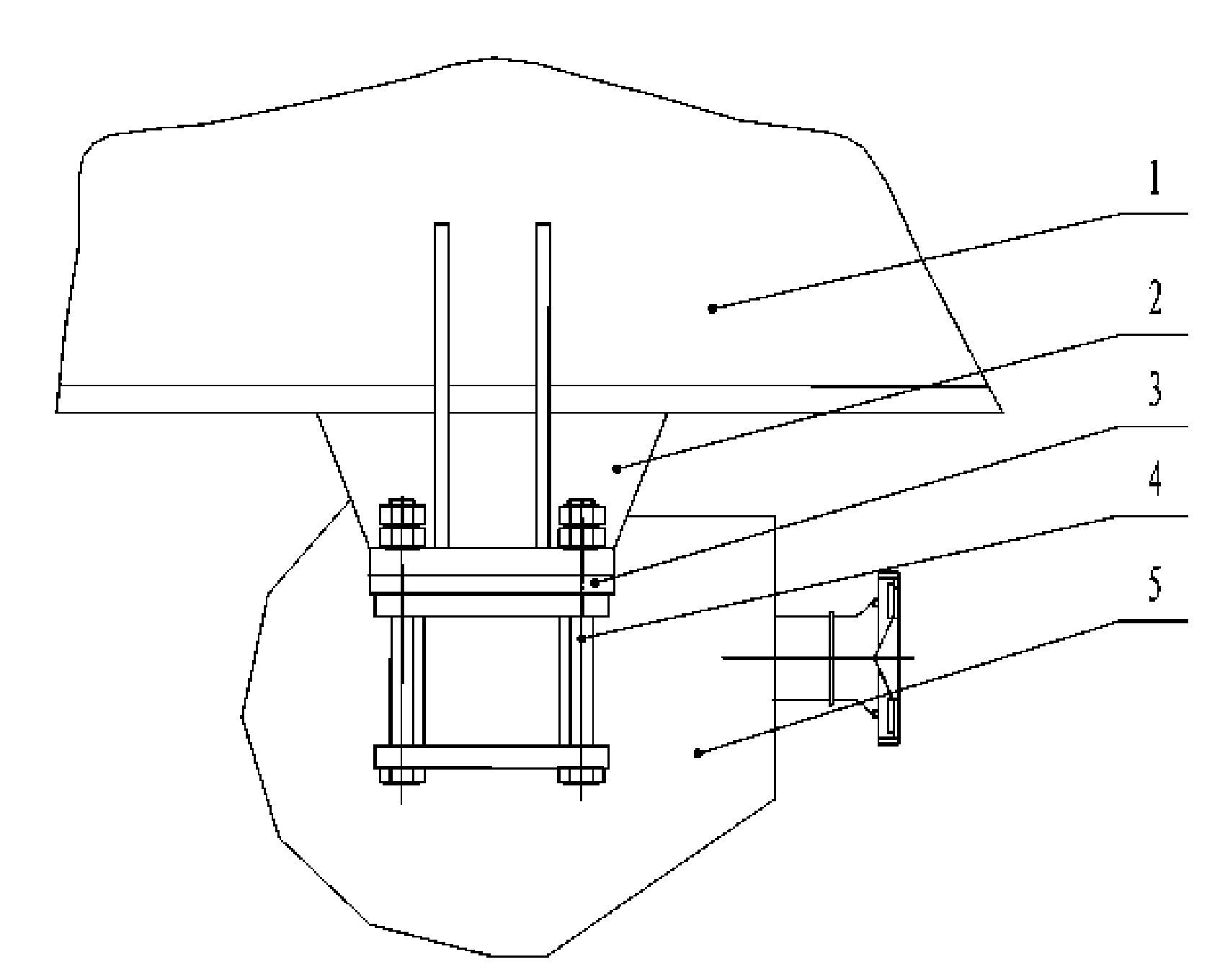
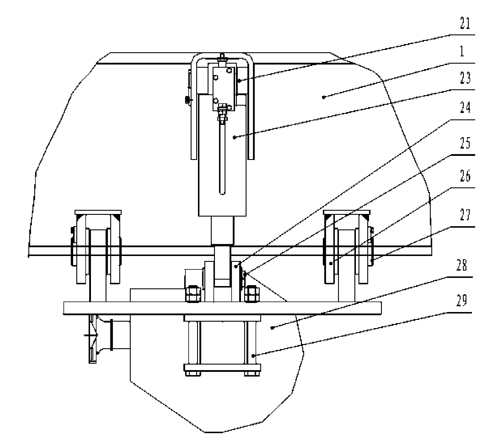
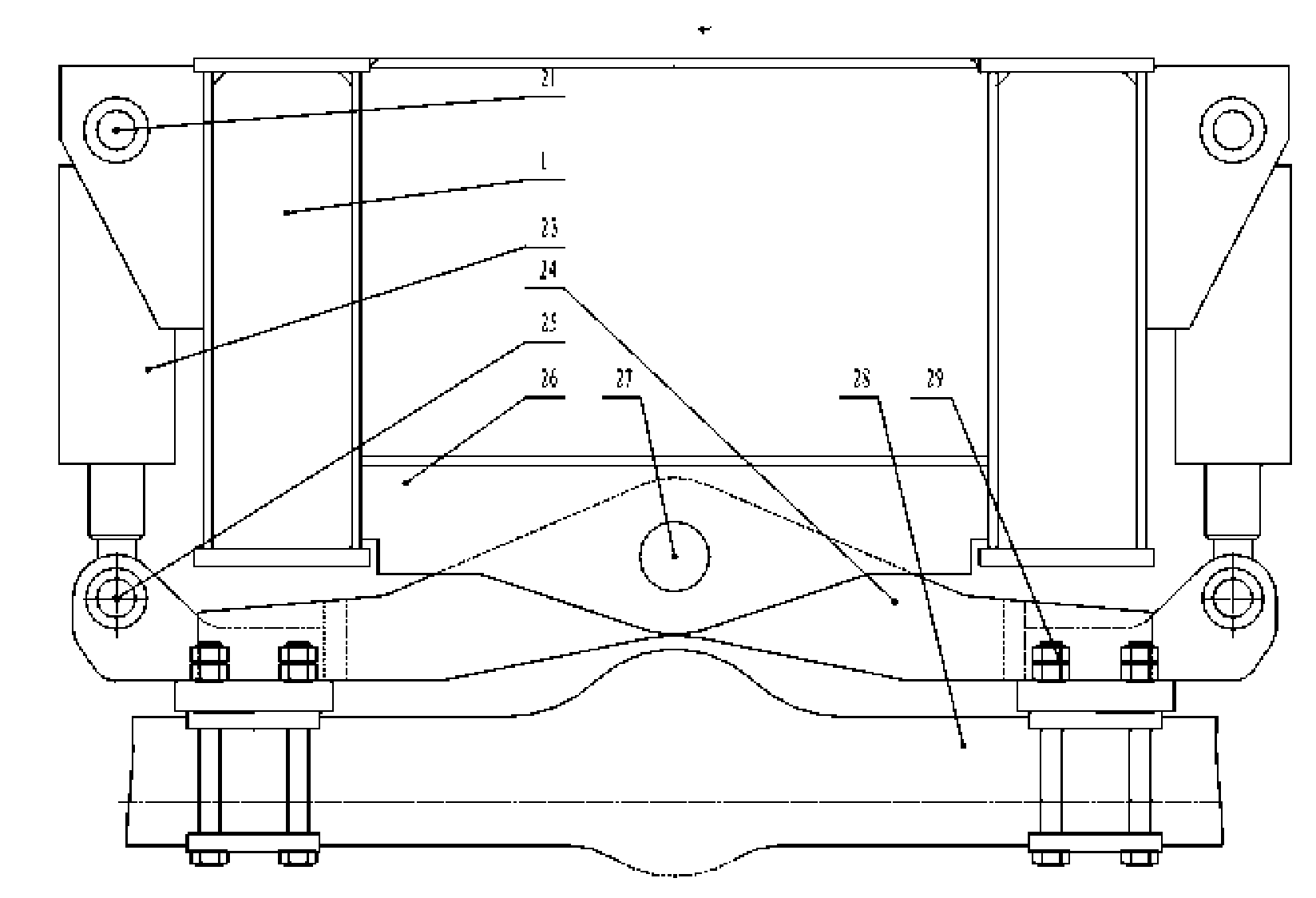
[0025] Specific embodiments of the present invention, such as figure 1 As shown, a crane swing suspension system includes an underframe 1 of a vehicle. A front suspension and a rear suspension 4 are installed on the underframe 1. The front suspension includes a front suspension support welded on the underframe 1. The seat 2 and the front suspension support 2 are rigidly connected and fixed to the front drive axle 5 through a shock absorbing pad 3 and a connecting bolt 4. Such as figure 2 , 3 As shown, the rear suspension 24 is hinged to the hinge support 26 on the chassis 1 via a pin 27, and the direction of the pin 27 is perpendicular to the direction of the wheel axis. Two locking cylinders 23 are symmetrically arranged on both sides of the pin shaft 27, and are installed between the rear suspension 24 and the underframe 1, preferably, such as figure 2 , 3 As shown, the cylinder block of the locking cylinder 23 is hinged to the underframe 1 through the upper hinge shaft 21 an...


PUM


Abstract

This invention discloses an oscillating suspension system of crane, including a chassis of vehicle, front and rear suspensions. It is characterized that the front suspension includes a front suspension support fixed to the chassis. The front suspension support is rigidly connected with a front drive bridge. The rear suspension is articulated with the support via a pin shaft. The direction of the pin shaft is perpendicular to the direction of a wheel shaft. Two locking oil tanks are symmetrically mounted at two sides of the pin shaft and between the rear suspension and the chassis. A connecting conduit of a chamber with rod and a chamber without rod of the locking oil tank is provided with a control valve set controlled by an electric control system. The rear suspension is rigidly connected with a rear drive bridge. The oscillating suspension system of crane provided by this invention is characterized that it can be flexibly applied to the crane to work at different pavements and under different bearing changes and it has simple structure, strong bearing ability, convenient distribution and low manufacturing cost.

Description

Technical field [0001] The invention relates to a heavy-duty vehicle, in particular to a suspension system of a crane. Background technique [0002] When the crane is under load traveling and other working conditions, the axle load of the whole machine is transferred, and the single axle load can reach 80,000 ~ 90,000 kg. The use of traditional leaf springs, spiral springs or oil-gas springs and other structural forms will make the suspension system components huge in size, high manufacturing costs, and occupy a large space, which cannot be realized in structural design. However, if the front and rear suspensions are fully rigidly connected, it will lead to: [0003] (1) The suspension system loses its shock absorption and buffering functions, and the ride and operation comfort of the whole machine is poor; [0004] (2) When the whole machine is driving and working on uneven roads, the single wheel will be suspended, which will cause the deterioration of wheel load distribution, ...

Claims


Application Information

Patent Timeline
IPC IPC(8): B66C23/62B60G13/00B60G17/00
Inventor 韩应奎陈志斌王美成何清荣陈殿春
Owner 四川长起起重设备有限公司
Why Eureka
Try Eureka