
Fault indirect diagnosis technique of rotating blade

A technology of rotating blades and diagnosis technology, applied in measurement devices, instruments, and mechanical devices, etc., can solve problems such as fluid flow field structure affecting blade topography, blade flying out, detection distortion, etc.

Active Publication Date: 2009-12-02
北京唐智科技发展有限公司
View PDF3 Cites 32 Cited by
  • Summary
  • Abstract
  • Description
  • Claims
  • Application Information

AI Technical Summary

Problems solved by technology

This not only changes the mechanical properties of the blade, distorts the detection, but also affects the shape of the blade surface and the flow field structure of the fluid; especially, once these additional detection devices fall off, it will cause catastrophic damage to the blade machine
Therefore, the vast majority of blade machines do not have blade fault diagnosis devices for online service, so that major accidents such as blade flying out occur from time to time

Method used


Image

  • Fault indirect diagnosis technique of rotating blade
  • Fault indirect diagnosis technique of rotating blade
  • Fault indirect diagnosis technique of rotating blade

Examples


Embodiment 1

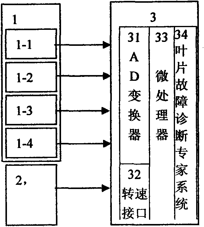
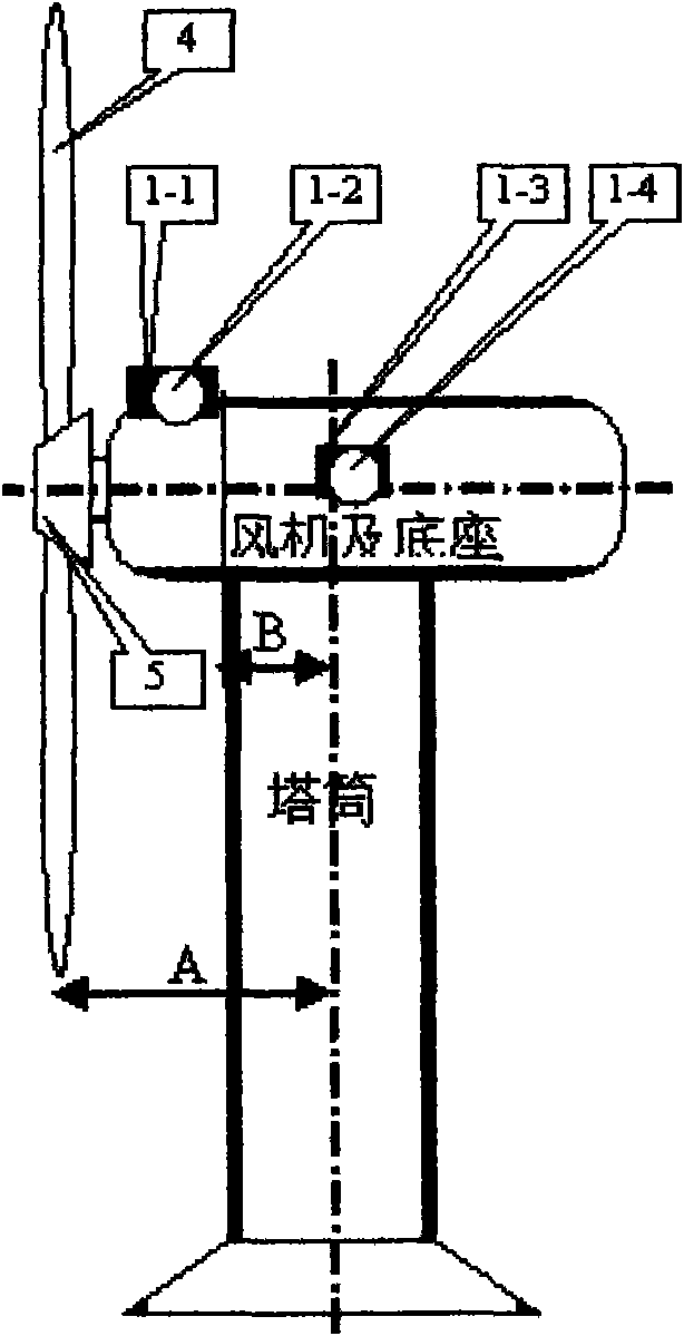
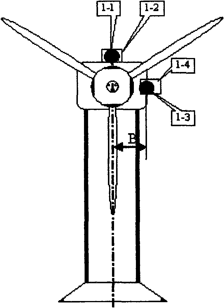
[0037] A rotor blade fault diagnosis device for a wind-driven generator, comprising vibration sensors 1-1, 1-2, 1-3, 1-4 installed on the fan and the base of the wind-driven generator; wherein, the vibration sensor 1-1 is installed Above or below the axis of the main shaft of the fan and the base, the distance from the center line of the fan tower is B, the sensitive axis points to the impeller end in front of the main shaft, and only the front and rear movement of the main shaft is sensitive, that is, the pitching vibration of the tower. The signal is Z1; among them, the vibration sensor 1-4 is installed on the left side of the main shaft axis of the fan and the base, the distance from the center line of the fan tower is B, the sensitive axis points to the right of the main shaft, and only the left and right swing of the main shaft is sensitive. The left and right vibrations of the tower; the output signal is Z4; among them, the vibration sensor 1-3 is installed on the left si...

Embodiment 2

[0059] A "Wind Power Generator Tower Operation Status Monitoring Device" (see the application number of the Chinese Patent Gazette: 200810030906.2), which discloses the vertical vibration of the main shaft of the wind turbine obtained by using its tower vibration detection sensor, or using its monitoring device to separate Y, transverse vibration P and torsional vibration NZ realize the fault diagnosis device for the rotating blade of the wind power generator.

[0060] The inventor applied for the invention patent application "Wind Power Generator Tower Operation Status Monitoring Device", which proposes to install sensors for detecting vibration inside the tower of the wind power generator tower: install dual-axis sensors E1 and E2 on the east side of the tower , the sensitive axes point to the north and east respectively; dual-axis sensors N1 and N2 are installed on the north side of the tower, and the sensitive axes point to the north and east respectively; a sensor for dete...

Embodiment 3

[0062] An indirect diagnosis and early warning technology for blade friction faults, further characterized in that the vibration information Z1, Z2, Z3, Z4 of the vibration sensor group 1 installed on the turbine blade and casing, or the vibration information P obtained by separation , Y, NZ signals, separately or superimposed, for hardware or software resonance demodulation transformation, when the rotating blade rubs against the stationary part during operation, the resonance demodulation outputs the resonance demodulation wave of the rubbing impact and eliminates all other low frequencies Vibration, the blade passes through the frequency vibration wave, and through FFT analysis, the resonance demodulation spectrum is obtained. The frequency FG of the first-order spectrum of the resonance demodulation is equal to the speed frequency FN, and the resonance demodulation spectrum has a multi-order spectrum k FG, where k is If it is a natural number, an early warning of blade grin...


PUM


Abstract

A fault indirect diagnosis technique of a rotating blade comprises a vibration impact sensor group which is installed on a static component of a blade machine, senses the vibration and impact caused by aerodynamic force and forcible touch and wear of rotor blades relative to static components and includes a rotational speed sensor for detecting operation frequency of the blade machine and a blade fault diagnosis device for analyzing signals reflecting blade fault information in the signals of the vibration sensor group relative to a signal rule of the rotational speed sensor, wherein the signals of the vibration impact sensor group including at least two vibration impact sensors and the signals of the rotational speed sensor with each rotator corresponding to one are connected to the blade fault diagnosis device, and blade fault diagnostician system software which is arranged in a microprocessor installed in the blade fault diagnosis device is used for diagnosing blade faults through vibration signals and rotational speed signals. The FFT analysis of the transverse vibration shock P of the blade machine in operation, the axial vibration shock Y of the blade machine and the torsional vibration NZ of a hanging or support device of the blade machine, and the analysis of the rotational speed frequency FN of the rotor are performed for recognizing blade faults by combining a computer technique with an electric sensor and the fault diagnostician system software. Various defects of prior art can be overcome.

Description

Technical field: [0001] The invention relates to an indirect diagnosis technology for rotating blade faults, which belongs to the category of mechanical fault detection and diagnosis technology, and is mainly used for on-line detection and diagnosis of blade machines (such as gas turbines, steam turbines, water turbines, wind power generators, The failure of the blades rotating with the main shaft in blowers, helicopter fan rotors, propeller aircraft blades, etc.). technical background: [0002] In the existing transportation, energy, and material industries, blade machines (such as aviation gas turbines, turbochargers for trains and ship internal combustion engines, steam turbines for thermal power and nuclear power, water turbines for hydropower, impellers for wind power generators, metallurgical and chemical equipment) Blowers, helicopter fan rotors, propeller blades, etc.) are usually the core equipment of enterprise equipment. The important components of these equipment...

Claims


Application Information

Patent Timeline
IPC IPC(8): G01N19/08
Inventor 唐德尧
Owner 北京唐智科技发展有限公司
Learn More