Device for adjusting light path and method thereof

A technology for optical path adjustment and optical axis direction, applied in optics, optical components, instruments, etc., can solve problems such as inaccurate judgment, disappearance of light spots, large errors, etc., achieve simple and easy operation, improve adjustment accuracy, and eliminate Abbe effect of error

Inactive Publication Date: 2009-12-02
PHOEBUS VISION OPTO ELECTRONICS TECH +1
View PDF0 Cites 29 Cited by
  • Summary
  • Abstract
  • Description
  • Claims
  • Application Information

AI Technical Summary

Problems solved by technology

However, the disadvantages of this method are: 1) The same point of the probe cannot receive laser irradiation for a long time, otherwise it will be saturated and the light spot will gradually disappear
Therefore, it is necessary to keep moving the human hand to change the position of the beam on the detector, and the shaking of the human hand will cause inaccurate judgment
2) When it is necessary to align the collimated light and the divergent light on the same axis, it is necessary to move the probe along the direction of the optical path and judge the spatial position of the spot of the divergent light, because the probe cannot accurately reflect the information of the spot (diameter, spatial position, etc.) , causing a larger error
This traditional method of using CCD to adjust the optical path overcomes the error caused by hand shaking caused by using the probe, but due to the axis of the measuring instrument, that is, the CCD106, and the object to be measured, that is, the helium-neon lasers 101 and 102, formed on the diffuser plate 105 The axes of the spots are not on the same line, this off-axis detection introduces the so-called "Abbe error", which is larger when correcting for diverging light to be on-axis with collimated light

Method used


Image

  • Device for adjusting light path and method thereof
  • Device for adjusting light path and method thereof
  • Device for adjusting light path and method thereof

Examples


Embodiment Construction

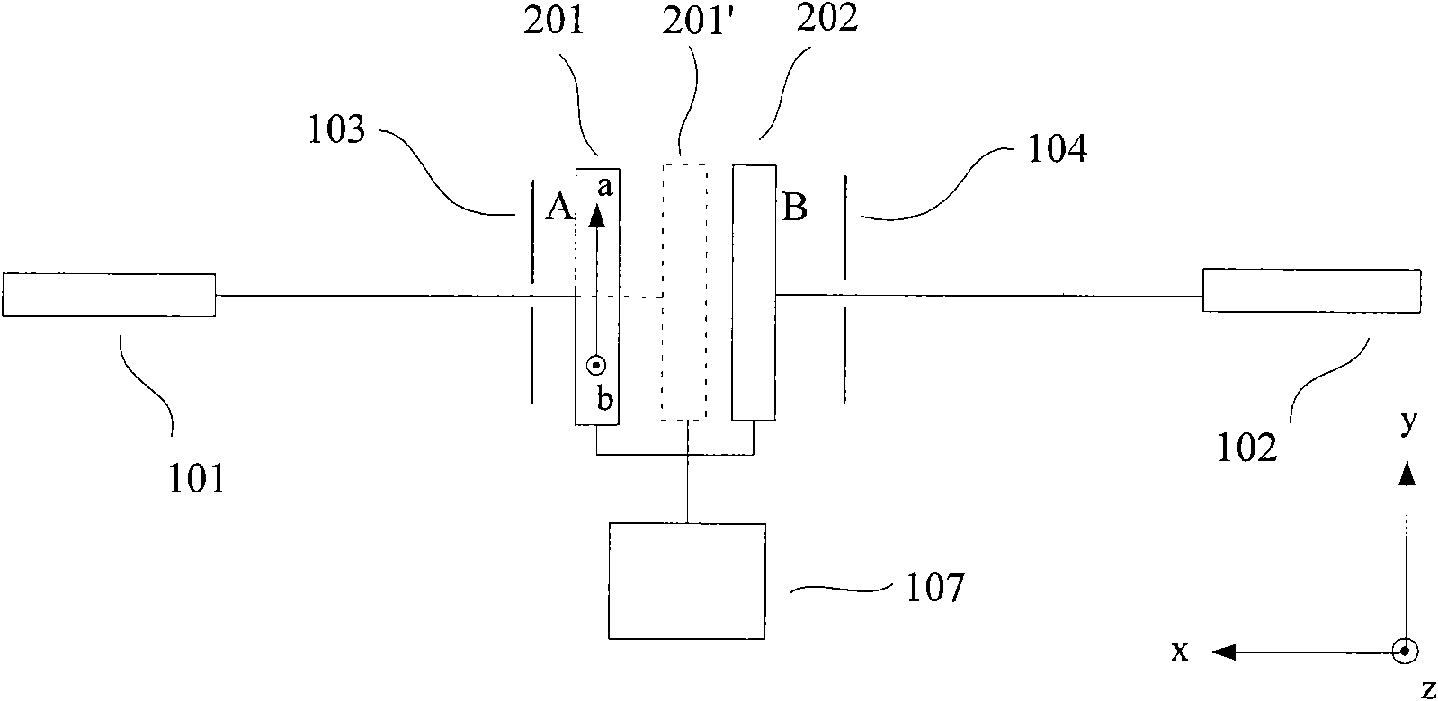
[0028] The content of the present invention will be further described in detail below in conjunction with the accompanying drawings and specific embodiments. figure 2 It is a schematic diagram of calibration of the device of the present invention in the collimation optical path, including He-Ne laser 101 , He-Ne laser 102 , pinhole diaphragm 103 , pinhole diaphragm 104 , CCD201 , CCD202 , and monitor 107 . The He-Ne lasers 101 and 102 are used to generate laser beams that irradiate the photosensitive surface of the CCD. The effect of described CCD201, CCD202 is to receive the light beam of helium-neon laser, and the photosensitive surface of described CCD201 and 202 itself has plane orthogonal coordinate system (marked as aob, when placing CCD201 and 202, make a and y direction roughly the same, b Roughly the same as the z direction, the a axis and the b axis are correspondingly displayed on the monitor), the CCD201 and 202 can convert the information of the spot position and...


PUM


Abstract

The invention provides a device for adjusting light path and a method thereof. The invention comprises a laser, a light spot detector and a monitor, wherein, the laser is used for generating laser beams irradiated to the light spot detector; the light spot detector is used for receiving the laser beams and then converting the received laser beam information to electrical signals and transmitting the electric signals to the monitor; and the monitor is connected with the light spot detector so as to convert received electrical signals to images. The light path adjusting method based on the device is characterized in coaxial measurement, and compared with traditional methods, the light path adjusting method of the invention is capable of eliminating Abbe error, improves adjustment precision, is easier to operate and is favorable to practically popularize.

Description

technical field [0001] The invention relates to the field of optical system adjustment, in particular to a device and method for optical path adjustment. Background technique [0002] Whether it is geometric optics experiment or physical optics experiment, it is often necessary to adjust the optical path related to the coaxial spherical system. A so-called coaxial spherical system comprises at least one optical system, such as a lens, comprising a refractive sphere. In order to obtain images with good quality, the main optical axes of each optical element in the coaxial spherical system should be on the same straight line. [0003] For safety reasons, the traditional adjustment method generally does not use human eyes to observe the optical path, and some lasers are not visible to human eyes, so generally the operator holds the probe (a detection plate that converts non-visible light into visible light, Also known as the photosensitive plate) to detect whether the beam pas...

Claims


Application Information

Patent Timeline
Patent Type & Authority Applications(China)
IPC IPC(8): G02B27/62G02B27/00
Inventor 王斌张勃毕勇成华
Owner PHOEBUS VISION OPTO ELECTRONICS TECH
Why Eureka
Try Eureka