
Integrated drive circuit for multifunctional electrical sound generation device

A sounding device and integrated drive technology, applied in stereo circuit arrangement, speech analysis, instrument, etc., can solve problems such as unavailable, increased assembly complexity, speaker noise, etc., to save assembly space, avoid complexity, and increase reliability Effect

Inactive Publication Date: 2009-12-02
AAC ACOUSTIC TECH (SHENZHEN) CO LTD +1
View PDF0 Cites 7 Cited by
  • Summary
  • Abstract
  • Description
  • Claims
  • Application Information

AI Technical Summary

Problems solved by technology

However, the output voltage of the power amplifier is generally about 2V, far exceeding the vibration voltage of the speaker by 0.4V, causing noise and damage to the speaker, resulting in vibration during calls or playback
For the purpose of protecting the vibration and sound generating device, measures are taken to limit the audio signal input to the power amplifier to limit the output power of the power amplifier, but it will not be able to obtain a higher volume; the second is to first pass one audio signal through a high-pass filter built with separate components Filter out its low-frequency components, and then send it to the multiplexer; the other audio signal is a low-amplitude, frequency Fv signal, and send it to the multiplexer; the signal controls the multiplexer to conduct it One signal is sent to the power amplifier, and the power amplifier drives the speaker to sound
However, this method requires additional operational amplifiers, multiplexers, resistors, and capacitors, which not only occupy a certain amount of PCB space, but also increase the volume of components, increase assembly complexity, reduce reliability, and increase costs; limited by the constraints of assembly space and Component errors cannot effectively filter out low-frequency components, which may easily lead to damage to the vibration and sound generating device, and are not suitable for the development of micro-devices

Method used


Image

  • Integrated drive circuit for multifunctional electrical sound generation device
  • Integrated drive circuit for multifunctional electrical sound generation device

Examples


Embodiment Construction

[0021] The present invention will be further described below in conjunction with the accompanying drawings and embodiments.

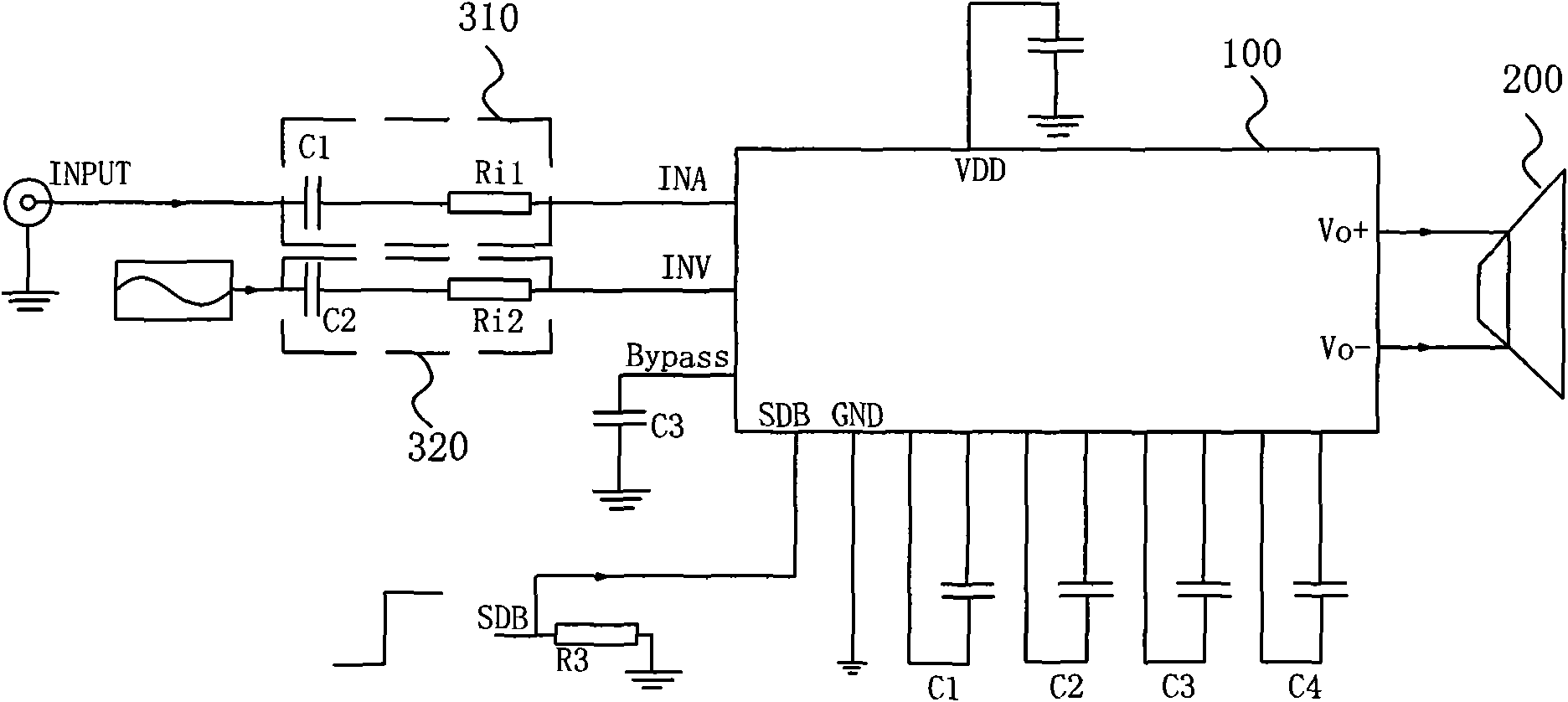
[0022] Such as figure 1 Shown is a schematic diagram of the application circuit of the present invention. The signal input to the driving circuit is divided into audio signal INA and vibration signal INV on channel 1. After circuit processing, the audio signal and vibration signal are independently or mixedly output to the vibration speaker 200, thereby realizing the driving of the vibration speaker 200.

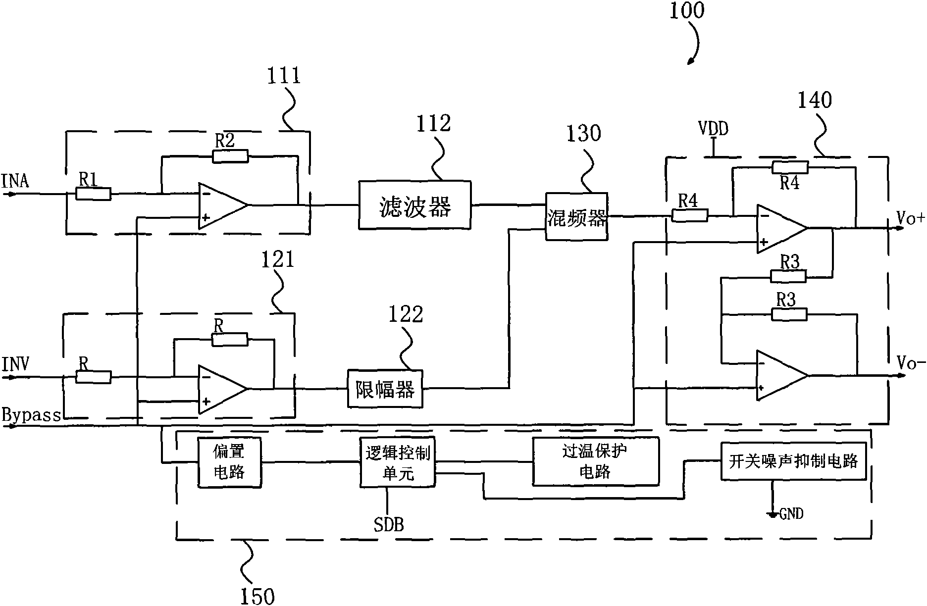
[0023] combine figure 2 As shown, the input signal is divided into two channels for processing, that is, the audio signal INA on channel one passes through a first-order high-pass filter 310 composed of a capacitor C1 and a resistor Ri1 connected in series, and its working characteristic is Fc=1 / (2π*C1 *(Ri1+R1)) The signal above the frequency can pass through, for example, the low frequency component below 20HZ is filtered out, and the C1 capacito...


PUM


Abstract

The invention relates to the field of electric and sound energy conversion devices, in particular to an integrated drive circuit for a multifunctional electrical sound generation device. A drive circuit is integrated in a micro chip, so large assembly space is saved, the complexity of the assembly of electric elements is avoided and product reliability is increased. In the circuit, a four-stage active high-pass filter and a front amplifier are integrated on the same chip, so the low frequency components, which can possibly bring vibration to loudspeakers, of an audio signal are effectively filtered out and the damages to the sound generation device are avoided. The drive circuit independently inputs and controls the audio signal and a vibration signal, thereby realizing the drive of the vibrating loudspeakers. Based on stable and mature standard CMOS process design, the drive circuit can be widely used on mobile phones, PDAs or various potable electronic devices.

Description

【Technical field】 [0001] The invention relates to the field of an electroacoustic energy conversion device, in particular to an integrated drive circuit for a multifunctional electric energy sound generating device. 【Background technique】 [0002] In a traditional portable electronic device, such as a mobile phone, the three functions of incoming call sound prompt, incoming call vibration prompt and telephone voice output need to be completed by three independent devices. Among them, a simple music sounder or a loudspeaker with a wider frequency response range is used to perform the sound prompt function of an incoming call; a micro DC vibration motor is used to perform the vibration prompt function; the voice output function of the telephone is completed by a receiver. However, the development trend of mobile phones is to be short, light and thin, and the more components there are, the more unfavorable it is to reduce the size of the mobile phone. Therefore, the various co...

Claims


Application Information

Patent Timeline
Patent Type & Authority Applications(China)
IPC IPC(8): H04R5/04G10L21/00
Inventor 杨勇刚冯劲松林海刘晓峰王晶
Owner AAC ACOUSTIC TECH (SHENZHEN) CO LTD
Learn More